


Form #43343330
–30– May 08
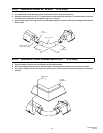
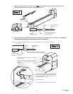
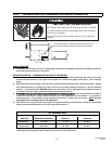
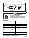
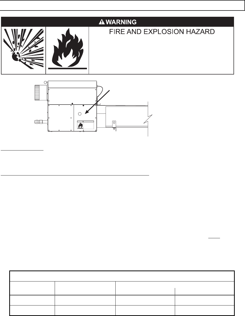
14.0) INSTRUCTIONS FOR PRESSURE TEST GAUGE CONNECTION
SIDE VIEW
43269050 Rev. A 03/08
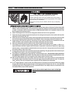
DANGER
Failure to do so may result in death,
serious injury or property damage
FIRE HAZARD
This access panel must be closed
tightly with all the necessary screws
during operation.
Never operate the heater with the
access panel open or removed.
Failure to do so may result in death, serious injury or property
damage.
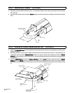
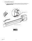
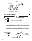
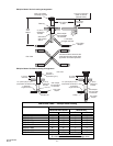
The access doors on either side of the burner must
be securely fastened before operating the heater.
The access panels must be closed tightly with all the necessary
screws during operation.
Never operate the heater with the access panel open or removed.
SUPPLY PRESSURE
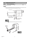
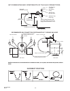
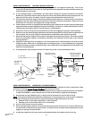
1. The installer will provide a 1/8” N.P.T. tapped plug, accessible for test gauge connection immediately upstream
of the gas supply connection to the heater.
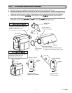
MANIFOLD PRESSURE – COMBINATION GAS VALVE IS FACTORY SET
1. Turn the gas valve to the “OFF” position. Remove the 1/8” plug from the combination gas valve at the outlet
pressure tap and connect a 1/8” nipple to the tapped hole. Connect the gauge to the nipple. Turn on the gas
supply.
2. With the main burner operating, check the burner manifold pressure using a water column manometer. Gauges
that measure pressure in pounds per square inch are not accurate enough to measure or set the manifold
pressure. All measurements MUST BE made when this heater and all other gas burning equipment that is
connected to the gas supply system are operating at maximum capacity.
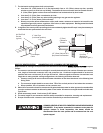
3. The combination gas valve is factory set and should not require adjustment. If full rate adjustment is required,
remove the cover screw. Using a small screwdriver, turn the adjustment screw clockwise to increase or
counterclockwise to decrease the gas pressure to the burner. Replace the cover screw. NOTE
: The step
opening pressure of this gas valve is not adjustable.
4. Check the burner at step pressure, observing burner ignition and flame characteristics. The burner should ignite
properly and without flashback to the orifice, and should remain lit.
GAS PRESSURE TABLE
SUPPLY PRESSURE
GAS TYPE MANIFOLD PRESSURE
Minimum* Maximum
Natural Gas 3.5” W.C. 5” W.C. 14” W.C.
Propane Gas 10.0” W.C. 11” W.C. 14” W.C.
* Minimum permissible gas supply pressure for purpose of input adjustment.