


Form #43343330
May 08 –23–
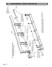
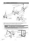
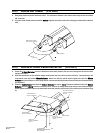
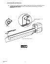
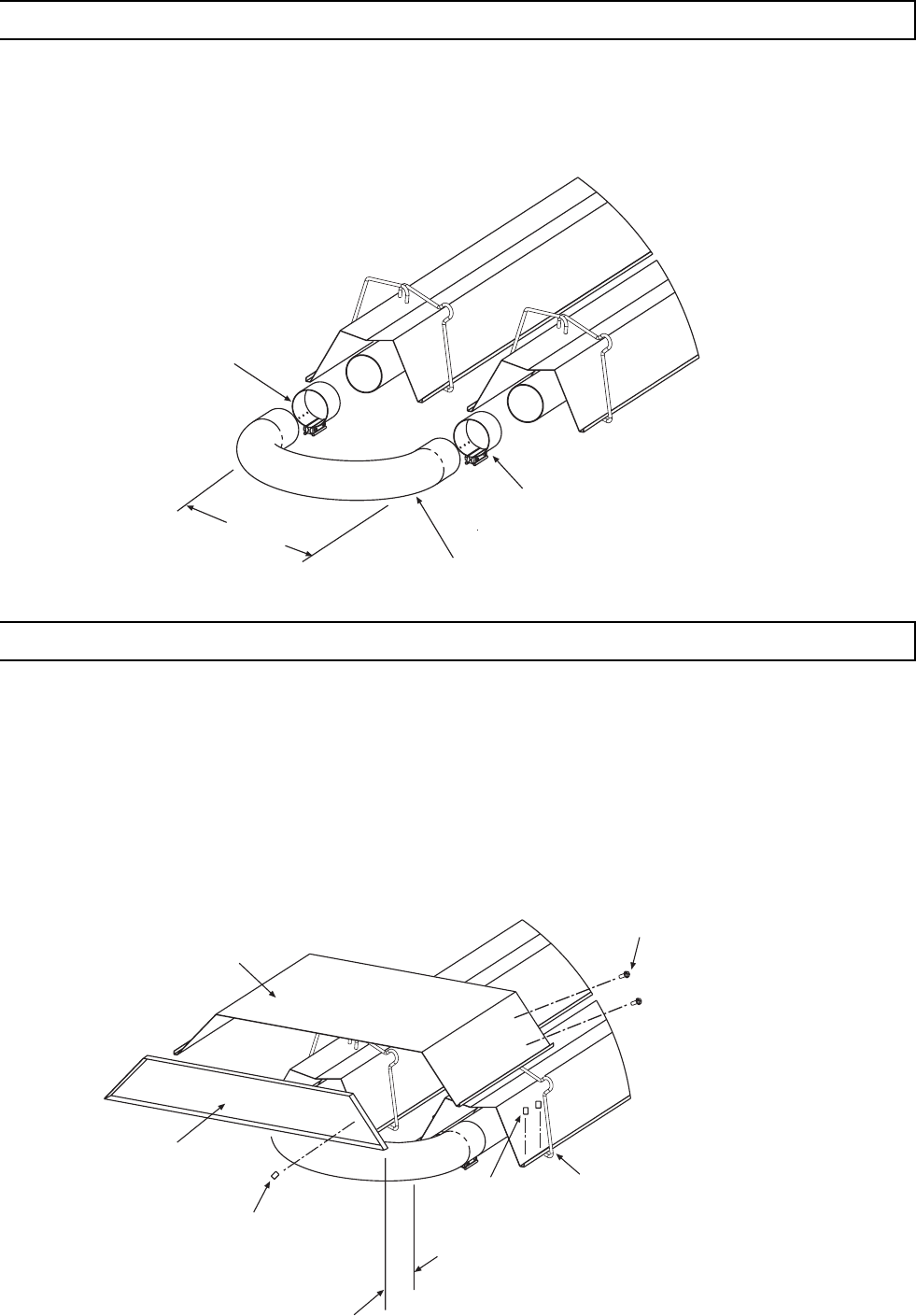
11.2) ADDING 180°U-Bend (PTU ONLY)
1. Hang body sections parallel with each other. The centerline distance from tube at each body section should be
18” as shown.
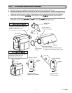
2. Join tube ends of body sections and the U-Bend together and secure with tube couplings as described in Section
10.1.
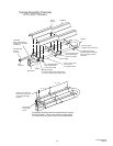
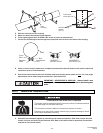
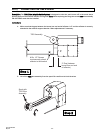
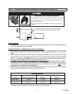
11.3) ADDING OPTIONAL U-BEND REFLECTOR (PTU ONLY)
1. Place the U-Bend Reflector over the reflectors of each body section with the end resting next to the tube wire
hangers as shown.
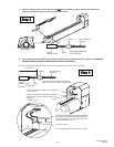
2. Slide the speed clips on the reflector edges towards the end of the body section reflectors. Two speed clips are
required for each side of the U-Bend Reflector. Make sure that the speed clips fit tightly over both the U-Bend
Reflector and the reflector on each body section. Use two self-drilling screws to permanently secure both sides to
the reflectors.
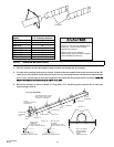
3. Place the End Reflector flush with the U-Bend Reflector as shown. Note: Clearance between end of the U-Bend
Reflector and the U-Bend must be a minimum of 1”. Secure by sliding speed clips onto the end reflector edges.
Evenly space the speed clips on the sides (two each side) and top (three each) of the reflectors to provide a snug
fit.
18
(457mm)
Tube Coupling
U-Bend
Self-Drilling Screws
(QTY-2 per coupling)
Speed Clip
Part No. 02266010
(QTY-7)
U-Bend Reflector
Part No. 43490000
Wire Hangers
Speed Clip
Part No. 02266010
(QTY-4)
End Reflector
Part No. 43490050
#10 Self-Drill Screws
Part No. 02189020
(QTY-4)
1 Clearance
(between end reflector
and u-bend)