


Form #43343330
–40– May 08
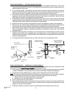
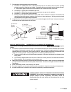
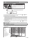
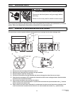
18.0) LIGHTING AND SHUTDOWN INSTRUCTIONS
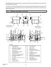
SIDE VIEW
43269050 Rev. A 03/08
DANGER
Failure to do so may result in death,
serious injury or property damage
FIRE HAZARD
This access panel must be closed
tightly with all the necessary screws
during operation.
Never operate the heater with the
access panel open or removed.
Failure to do so may result in death, serious injury or property
damage.
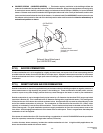
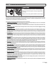
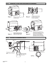
The access doors on either side of the burner must
be securely fastened before operating the heater.
The access panels must be closed tightly with all the necessary
screws during operation.
Never operate the heater with the access panel open or removed.
1) Turn on the gas and electrical supply. Rotate the gas valve knob counter-clockwise to the “ON” position.
2) Set the thermostat to call for heat. The blower motor will energize.
3) Ignition should occur after the 15-second pre-purge.
4) If the burner fails to light, or flame is not detected during the first trial for ignition (a period of approximately 15
seconds) the gas valve is de-energized and the control goes through an inter-purge delay of approximately 60
seconds before another ignition attempt. The control will attempt two additional ignition trials before going into
lockout, and the valve relay will be de-energized immediately. The blower will be turned off following a post-purge
period of approximately 30 seconds.
5) If the heater does not light, manually reset the thermostat or shut off power completely for 5 minutes before
attempting to relight.
6) To permanently shut down the heater, rotate the gas valve knob clockwise to the “OFF” position and turn off
the gas and electrical supply.
NOTE: THE LIGHTING AND SHUTDOWN INSTRUCTIONS ARE ALSO SHOWN ON THE PERMANENT NAMEPLATE LABEL
ATTACHED TO THE HEATER.
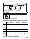
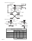
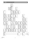
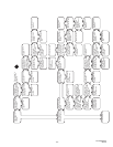
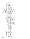
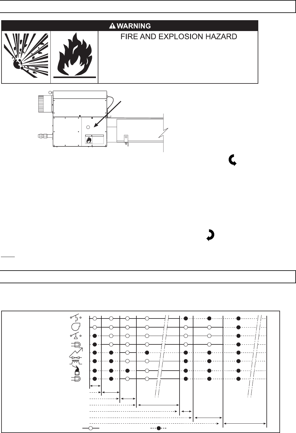
19.0) SEQUENCE OF OPERATION
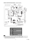
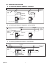
The chart below shows the sequence of operation for the normal operating cycle of the PTS/PTU when connected
to a permanent 120V power supply and the heater is turned on and off by a remote 24V thermostat. (Electrical
connection diagram C).
T0 T1 T2 T3 T4 T5 T7
Call for heat, Thermostat on
15 secs pre-purge
15 secs trial for ignition
Normal operation flame sensing
Heater OFF
Thermostat (turn off)
30 secs post-purge
1
T6
Thermostat
Blower
Red power light
Ignition
Air switch
Gas valve
Flame sensing
Amber valve light
Function ON Function OFF