


Form #43343330
–34– May 08
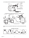
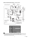
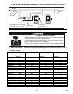
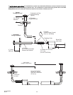
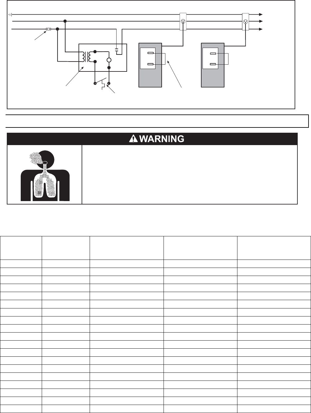
D. LOW VOLTAGE (24V) THERMOSTAT CONNECTIONS – MULTIPLE HEATERS (utilizing a fan center relay)
Burner Control Box
Ground
N Neutral
L1 Hot (120V)
Low voltage
thermostat (24V)
Continue To
Additional
Heaters
Power Supply
Cord (120V)
Receptacle
TH
C
Jumper factory
installed for optional
24V thermostat
Fused
Disconnect
switch
24V
coil
C
R
G
NO
TH
C
Fan Center Relay Part No. 30169000
Contact Rating: 120V, 40VA, 12A
(maximum of 6 heaters per relay)
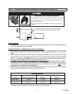
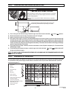
16.0) VENTING
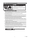
Failure to do so may result in death, serious injury, property damage or illness
from Carbon Monoxide poisoning.
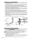
Heaters installed in an unvented mode require a minimum ventilation flow of
4 CFM per 1,000 Btu/hr of total installed capacity.
In buildings with airborne contamination such as poultry houses the heater
must be installed with fresh air for combustion.
CARBON MONOXIDE HAZARD
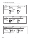
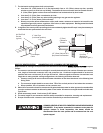
A. BASIC FLUE VENTING — Venting must comply with the latest edition of the National Fuel Gas Code (ANSI
Z223.1-latest edition) or the authority having jurisdiction. Other venting references are in the equipment volume of
the ASHRAE Handbook.
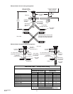
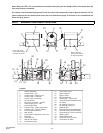
Vent lengths shown in the table are for horizontal and vertical venting. If a longer length of vertical or horizontal
venting is required contact the manufacturer for assistance with vent sizing.
Model Heat
exchanger
length ft
Maximum vent length ft.
(4” diameter)
Maximum Fresh air
intake length ft (4”
diameter)
Max. combination of
fresh air and vent ft. (4”
diameter)
PTS/U 40 20 45 50 75
PTS/U 50 20 45 50 75
PTS/U 50 30 35 40 65
PTS/U 75 20 45 50 75
PTS/U 75 30 35 40 65
PTS/U 100 30 45 50 75
PTS/U 100 40 35 40 65
PTS/U 125 30 60 50 75
PTS/U 125 40 50 40 65
PTS/U 125 50 40 30 55
PTS/U 150 40 60 50 75
PTS/U 150 50 50 40 65
PTS/U 150 60 40 30 55
PTS/U 175 50 60 50 75
PTS/U 175 60 50 40 65
PTS/U 175 70 40 30 55
PTS/U 200 50 60 40 65
PTS/U 200 60 50 30 55
PTS/U 200 70 40 30 45