


4-1
4. INSTALLATION OF ARP-10 (OPTION)
NOTICE
This option is not available
with 48 rpm scanner unit.
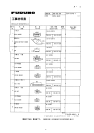
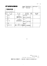
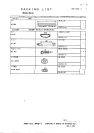
4.1 Necessary Parts
emaNepyT.oNedoCytQ
draoB01-PRA7009P81039-674-8001
recapS02-QS056-108-0004
rehsaWgnirpSW1915C3M402-468-0004
wercSdaeHnaPW0072C8x3M404-188-0006
wercSdaeHnaP
*rehsaw/w
8x3M
01MRWS
477-508-0003
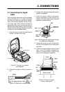
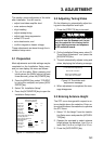
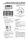
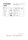
4.2 Mounting
1. Turn off the power. Remove the cover
from the display unit as follows:
1 Unfasten four binding screws (M4 x 10).
2 Unfasten six binding screws (M3 x 10).
3 Remove three rubber covers to unfas-
ten three hex nuts.
4 Loosen two hex nuts.
1
1
1
1
2
2
3
4
Figure 4-1 Display unit, rear view
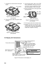
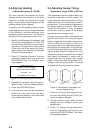
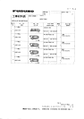
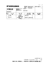
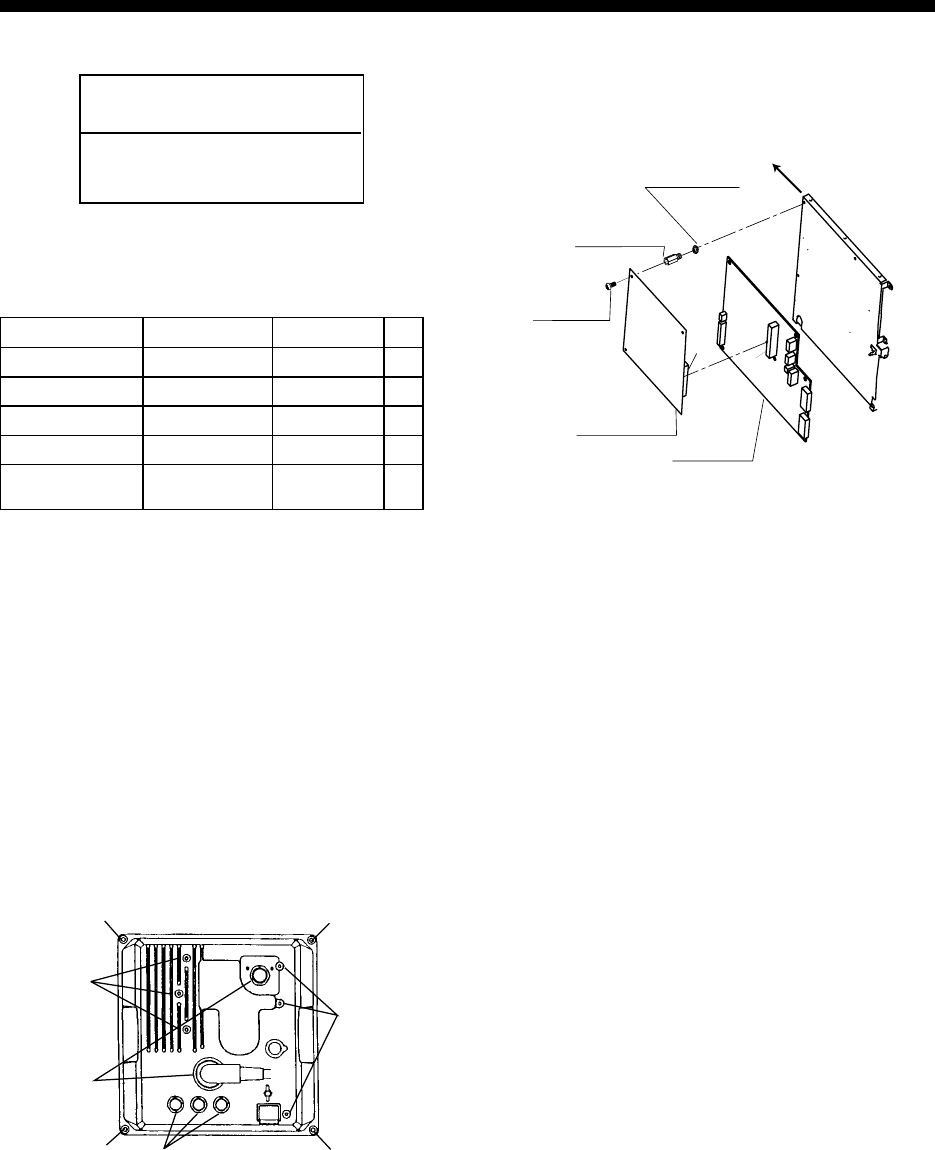
2. Fasten the ARP-10 Board to the right-
hand chassis of the display unit, using the
pan head spacers, screws, and washers
(supplied) as follows.
(1)Attach three spacers.
(2)Attach the P107 connector from the
ARP-10 Board to J107 connector on
the SPU Board.
(3)Faster the ARP-10 Board to the chas-
sis with three pan head screws and
springs washers.
$
$
Spacer
SQ-20 3 pcs.
Spring Washer
M3 3 pcs.
Pan Head
Screw
M3 x 8 3 pcs.
J107
P107
SPU Board
SPU9211
ARP-10 Board
18P9007
Front
Note: Remaining hardware may be discarded.
Figure 4-2 How to mount the
ARP-10 Board
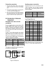
4.3 Adjustments
Input signal
1. Connect the gyrocompass. Turn on the
radar and transmit.
2. Press the [MENU] key and select the
OTHERS menu
3. Select “23. Self Test” and press the [ACQ/
ENTER] key. Confirm that the ARP-10 test
results show OK for SPEED, COURSE,
TRIGGER< BP and HP.
Video signal
Confirm the following on the ARP-10 test dis-
play:
• Video is “OK.”
• Adjust the GAIN, A/C and A/C RAIN con-
trols so FE-DATA1 and FE-DATA2 indi-
cations on the ARP-10 TEST show less
than 1,000. Also, raise/lower the gain
while watching the FE-DATA1 and FE-
DATA2 indications. Confirm that the FE-
DATA1 and FE-DATA2 indications rise/
lower according to GAIN control adjust-
ment.
*Not used.