


2-2
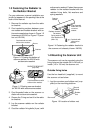
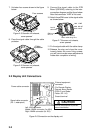
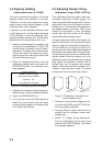
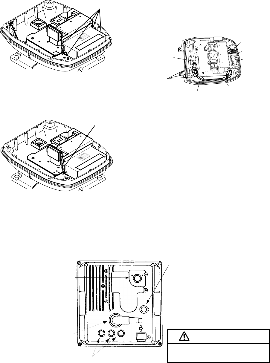
7. Unfasten four screws shown in the figure
below.
Four screws
Figure 2-5 Scanner unit chassis,
cover opened
8. Pass the signal cable through the cable
protector.
Cable
protector
Figure 2-6 Scanner unit chassis,
cover opened
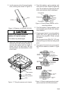
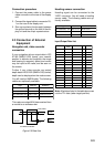
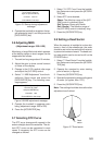
9. Connect the signal cable to the RTB
Board (03P9249), referring to the inter-
connection diagram and the figure below.
Note that connector VH2P is not used.
10.Attach three EMI cores to the signal cable
as shown below.
Route cable along here.
Lead in
cable here.
J821 VH9P
J824 NH13P
J823 VH4P
EMI core
RFC-13
Clamp
Figure 2-7 Scanner unit chassis,
cover opened
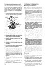
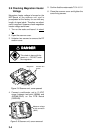
11. Fix the signal cable with the cable clamp.
12.Release the stay and close the cover.
Loosely fasten the cover fixing screws;
you will have to make some adjustments
inside after completion of wiring.
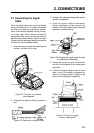
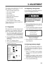
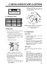
2.2 Display Unit Connections
CAUTION
Ground the equipment to prevent
mutual interference.
Power cable connector
Ground terminal
External equipment
connector
Signal cable connector
(DJ-1, waterproof)
Left: HDG connector
Middle: NMEA connector (for NAV)
Right: NMEA connector (for E/S)
(For Remote Display,
External Alarm Buzzer
OP03-21 and Radar
Plotter, RP-110)
Figure 2-8 Connection on the display unit