


2-1
2.1 Connecting the Signal
Cable
Only the signal cable runs from the display
unit to the scanner unit. In order to minimize
the chance of picking up electrical interfer-
ence, avoid where possible routing the sig-
nal cable near other onboard electrical
equipment. Also, avoid running the cable in
parallel with power cables. Pass the cable
through the hole and apply sealing compound
around the hole for waterproofing.
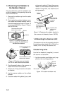
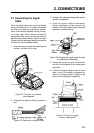
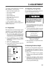
1. Open the scanner cover by loosening two
screws, and then fix the stay.
Stay
Cable gland
Fixing screw
Figure 2-1 Scanner unit chassis,
cover opened
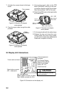
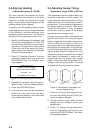
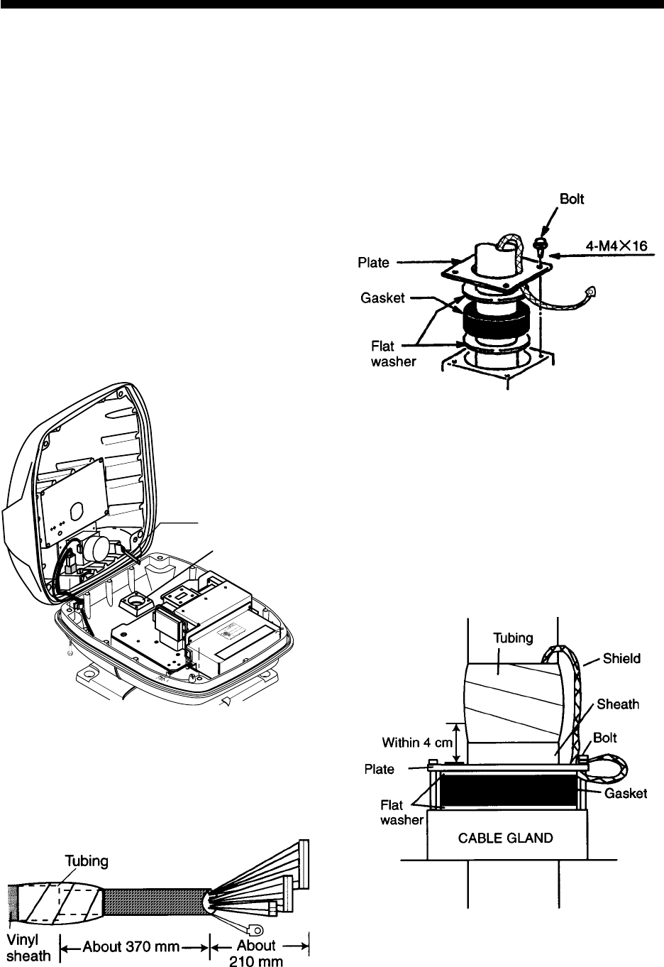
2. Fabricate the signal cable as shown be-
low.
Figure 2-2 Fabrication of signal cable
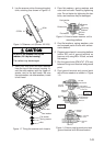
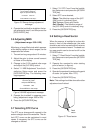
3. Unfasten the cable gland assembly (plate,
gasket, flat washer).
4. Pass the signal cable w/connector
through the bottom of the scanner unit
chassis. Pass the cable through the gland
assembly as shown below.
Figure 2-3 Passing the signal cable through
the cable gland assembly
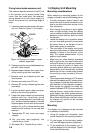
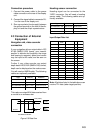
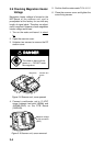
5. Fasten the crimp-on lug on the shield to
one of the fixing bolts of the cable gland
assembly.
6. Position the signal cable so that no more
than 4 cm of the sheath is exposed as
shown in the figure below. Tighten fixing
bolts on the cable gland assembly.
Figure 2-4 How to fix signal
cable in cable gland
2. CONNECTIONS