


www.fmiproducts.com
125160-01A20
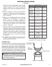
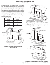
1/2" Thick Cement Board Dimensions
Model A1 A2 B1 B2
MM63 67" 28" 60" 23"
SUPPORTING FLOOR SYSTEMS INSTALLATION
Continued
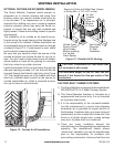
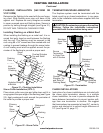
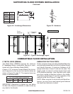
Figure 29 - Anchorage Dimensions Figure 30 - Hardware
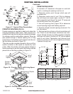
Figure 31 - Typical Anchorage Layout
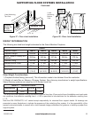
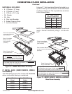
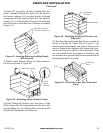
COMBUSTIBLE FLOOR INSTALLATION
8" METAL BASE (MMB63)
The Metal Base (MMB63) ensures the minimum
8" clearance above combustible ooring is main-
tained with Grand Meridian Model MM63.
A layer of 1/2" minimum Cement Board (Not Includ-
ed) is required on the top and mid section below as
shown in Figure 32, page 21. The required sizes are
shown in the table below.
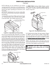
IMPORTANT: Remember to tighten up nuts below
the oor after replace installation in order to take up
any slack in the threads.
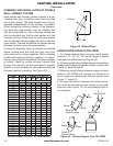
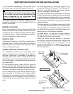
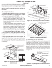
EMBER PROTECTOR STRIPS:
Ember protector strips (included with Metal Base Kit)
are required between the front of the Fireplace Hearth
and Hearth Extension. A minimum thickness of 26
gauge metal strip at least 4" wide can be used. The
length needs to extend 2 inches beyond each side
of the replace opening. If two strips are used, make
sure they overlap at least two inches in the middle.
The strip is placed about 2" into the underside of the
platform at the front (Figure 10, page 10).
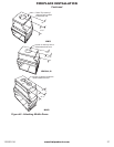
NOTE: When using an on-site constructed hearth ex-
tension, you may use a sand-cement grout between
the hearth and extension instead.
F
10"
4"
A
Model A
MM33 32 ¾"
MM39 38 ¾"
MM44 43 ¾"
MM49 48 ¾"
MM63 62 ¾"
2” min
clearance
Fireplace
outline
10”
EXAMPLE ONLY
SECTION VIEW
ROTATED 90CW