


www.fmiproducts.com
125160-01A18
SUPPORTING FLOOR SYSTEM INSTALLATION
It is the ultimate responsibility of the installer to en-
sure that proper concrete slab supports are used.
WARNING to the licensed design professional
and/or building contractor: It is your responsibility
to be certain that the Grand Meridian can be
properly supported by the combustible oor
system on which the replace will rest.
For replace support foundations installed on con-
crete refer to Appendix I and II (pages 42 & 43) for
specic instructions.
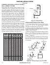
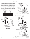
REBAR LOCATIONS
Lay-out the position of the replace and drill holes
where the rebar will be located. Secure the #3 rebar
4 inches into the concrete foundation with ITW Epoxy
or Simpson Epoxy. Follow manufacturer’s instruc-
tions for installation of rebar into slab.
WOOD FLOOR
Anchorage of replace to wood oor construction is
required. Refer to Figure 29 on page 20 for anchor-
age dimensions. Four anchors are required to attach
to the sub-ooring framing.
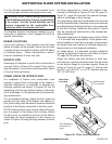
CRAWL SPACE OR UPPER FLOOR:
For installation of rebox over combustible crawl
spaces or upper oors, anchorage of the rebox is
required. Illustrations of examples of possible an-
chorage methods are shown in Figures 26 thru 28
depending upon the type of oor framing. Final meth-
od of anchorage is to be determined by licensed de-
sign professional.
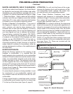
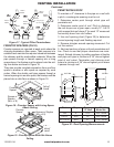
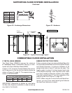
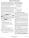
For conventional framing, where the oor joists are
parallel with the sides of the rebox, the addition of
oor joists to align with the anchor brackets allows the
brackets to be directly connected to the oor joists.
NOTE: Additional oor joists may be required to sup-
port the weight of the rebox and chimney. Where
the oor joists run parallel to the front of the rebox,
anchorage can be accomplished in like manner as
shown in Figure 26 using blocking between the oor
joist.
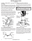
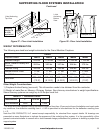
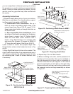
For oors supported by I-Joists, the method of an-
chorage is illustrated in Figures 27 and 28, page 19.
Figure 31, page 20 illustrates the general arrange-
ment of anchorage to oor framing.
It is important to take into consideration that the load
for the Grand Meridian Fireplace must be considered
as additional dead load that will have to be supported
by the oor framing. Additional oor joists or I-joists
may be required as determined by the licensed de-
sign professional.
The dead weights for the replace are noted in Table
I. It is the task and responsibility of the general con-
tractor/installer to see that the proper reinforcement
for weight loads are made by a licensed design pro-
fessional prior to the replace installation.
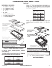
As stated above, it is desirable to place additional
framing for alignment of anchor rods. Refer to Figure
29, page 20 for anchor rod locations.
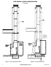
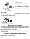
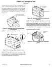
Attach the rebox side wall anchors to steel sup-
port frame by inserting all-thread rods through holes
on the bottom ange on the steel support frame as
shown in Figure 32 and 33, page 21. Secure with
two Ø 2" o.d. x Ø 9/16" i.d. x 0.10" Washers and two
1/2"-13 UNC Nuts.
Floor Sheathing
not shown for
clarity
Metal Base
Assembly
EXAMPLE ONLY
2X FLOOR JOIST
2X FLOOR JOIST
A35 Brackets
(16 required)
Figure 26 - Floor Joist Installation