


www.fmiproducts.com
119315-01D12
INSTALLATION
Continued
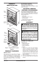
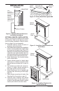
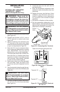
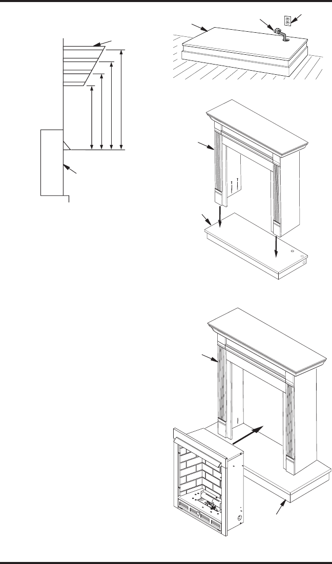
Mantel Shelf
3
1
/
4
"
6"
9"
18"
3/4"
1"
3"
9"
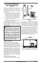
Note:
All vertical
measurements
are from top of
fireplace
opening to
bottom of
mantel shelf. All
measurements
are in inches.
Figure 9 - Minimum Mantel Clearances
for Built-In Installation
Refer to instructions provided with the mantel
for assembly. Refer to the following instruc-
tions for system installation. Refer to instruc-
tions on page 6 for hood assembly.
1. Assemble cabinet mantel as shown in
accessory instruction sheet.
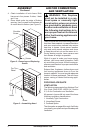
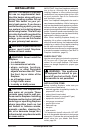
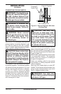
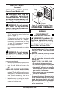
2. Place hearth base against wall at installation
location. Cut an access hole in hearth base
to run gas line to replace (see Figure 10).
Make sure to locate access hole so cabinet
mantel will cover it when installed. Note: You
can secure base to oor using wood screws.
Countersink screw heads and putty over.
3. Route exible gas line through access
hole in hearth base.
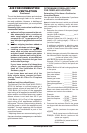
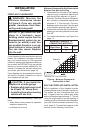
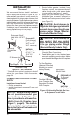
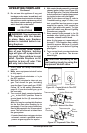
4. Center cabinet mantel on hearth base
(see Figure 11). Make sure mantel is ush
against wall and centered left to right on
base.
5. Use hardware provided with mantel ac-
cessory to attach mantel assembly to
base (see mantel instruction sheet).
6. Attach exible gas line to replace gas
regulator. See Connecting to Gas Supply,
page 13.
7. Check all gas connections for leaks. See
Checking Gas Connections, page 15.
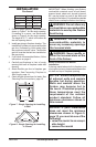
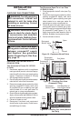
8. Carefully insert fireplace into cabinet
mantel (see Figure 12). Be careful not to
scratch or damage hearth base or cabinet
mantel (see manual instruction sheet.
Side of Firebox
Figure 10 - Placing Hearth Base Against Wall
Hearth
Base
Electrical
Outlet
Pipe and Gas
Shutoff Valve
Figure 11 - Installing Cabinet Mantel onto
Hearth Base
Cabinet
Mantel
Hearth
Base
Figure 12 - Installing Fireplace into
Mantel Assembly
Cabinet
Mantel
Hearth Base