


www.fmiproducts.com
119315-01D 11
INSTALLATION
Continued
Actual Framing
Height 23
3
/4" 22
1
/4"
Front Width 19
3
/4" 17
1
/2"
Depth 8
7
/8" 8
7
/8"
Bottom 0" 0"
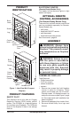
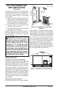
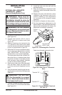
1. Frame in rough opening. Use dimensions
shown in Figure 7 for the rough opening.
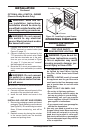
If installing in a corner, use dimensions
shown in Figure 8 for the rough opening.
The height is 22
1
/4" which is the same as
the wall opening above.
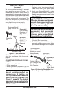
2. Install gas piping to replace location. This
installation includes an approved exible
gas line (if allowed by local codes) after
the equipment shutoff valve. The exible
gas line must be the last item installed on
the gas piping.
3. If you have not assembled rebox, follow
instructions on page 6.
4. Carefully set replace in front of rough
opening with back of replace inside wall
opening.
5. Attach exible gas line to replace gas
regulator. See Connecting Fireplace to
Gas Supply, page 14.
6. Check all gas connections for leaks. See
Checking Gas Connections, page 15.
17
1
/
2
"
22
1
/
4
"
8
7
/
8
"
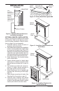
Figure 8 - Rough Opening for Installing
in Corner
Figure 7 - Rough Opening for Installing
in Wall
29
7
/
8
"
21
1
/
8
"
42
1
/
4
"
17
1
/
2
"
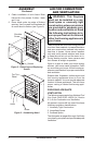
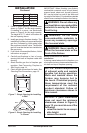
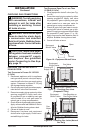
IMPORTANT: When nishing your rebox,
combustible materials such as wall board,
gypsum board, sheet rock, drywall, plywood,
etc. may be butted up next to the sides and
top edge of the rebox. Combustible materials
should never overlap the rebox front facing.
WARNING: Do not allow any
WARNING: Do not allow
WARNING: Never modify or
cover the louvered slots on the
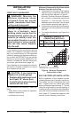
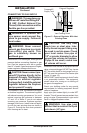
Mantel Clearances for Built-In
Installation
If placing mantel above built-in replace, you
must meet minimum clearance between man-
tel shelf and top of replace opening.
minimum clearances shown in
NOTICE: If your installation
does not meet the minimum
-