


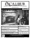

Excalibur
®
P95-3 Zero Clearance Direct Vent Gas Fireplace 7
INSTALLATION
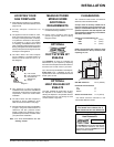
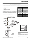
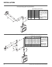
Side Wall Clearance 6-1/2" (165mm)
Horizontal Vent Clearances
Top 3"
Side 2"
Bottom 2"
Vertical Vent Clearances 1-1/4" (32mm)
* see mantle clearance instructions in the
"Combustible Mantels" section.
CLEARANCES
The clearances listed below are Minimum
distances unless otherwise stated:
A major cause of chimney related fi res is
failure to maintain required clearances (air
space) to combustible materials. It is of the
greatest importance that this fi replace and
vent system be installed only in accordance
with these instructions.
Clearance to Combustibles from:
Back 0" (0mm)
Side 0" (0mm)
Floor 0" (0mm)
NOTE: The minimum fl oor clearance must
be maintained from the top surface of the
carpeting, tile, etc.
LOCATING YOUR
GAS FIREPLACE
1) When selecting a location for your fi replace,
ensure that the clearances outlined on this
page are met.
2) Provide adequate clearances for
servicing.
3) The appliance must be installed on a fl at,
solid, continuous surface (e.g. wood, metal,
concrete). This may be the fl oor, or raised up
on a platform to enhance its visual impact.
If the appliance is going to be installed
on carpeting, combustible linoleum tile or
other combustible material other than wood
fl ooring, the appliance must be installed on a
metal or wood panel extending the full width
and depth of the appliance.
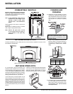
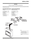
4) The P95-3 Direct Vent Gas Fireplace
can be installed in a recessed position or
framed out into the room as in A, B, C, D.
See Diagram 1.
MANUFACTURED
MOBILE HOME
ADDITIONAL
REQUIREMENTS
1) Ensure that structural members are not cut
or weakened during installation.
2) Ensure proper grounding using the #8
ground lug provided. See the "Wiring
Diagram" section.
5) This appliance is Listed for bedroom
installations when used with a Listed Millivolt
Thermostat. Some areas may have further
requirements, check local codes before
installation.
6) The P95-3 Direct Vent Gas Fireplace is
approved for alcove installations, which
meet the clearances listed on this page.
7) We recommend that you plan your installation
on paper using exact measurements for
clearances and fl oor protection before
actually installing this appliance. Have a
qualifi ed inspector, dealer, or installer review
your plans before installation.
Note: For vent terminations see the
"Venting" section.
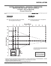
Diagram 1
A) Flat on Wall
B) Flat on Wall Corner
C) Recessed into
Wall/Alcove
D) Corner
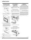
OPTIONAL
HEATWAVE
DUCT SYSTEM KIT
#946-556
The HeatWave Air Duct Kit increases the
effectiveness of your fi replace by dispersing
warm air from the fi replace to remote locations in
the same room or other rooms in your home.
Up to two kits may be installed on the fi replace.
Please Note: Only 1 HeatWave kit may be
operated at one time. This includes the internal
blower option as well.
OPTIONAL
HEAT RELEASE KIT
#946-570
The Heat Release Kit expels warm air from
the fi replace to the outside of the building,
allowing the fi replace to be operated with less
heat entering the room. The kit may be used
on either the left or right side.
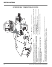
WARNING:
Fire hazard is an extreme risk if
these clearances are not adhered to.
Clearances for HeatWave and
Heat Release Kit
Heat Release Kit
The HeatWave Duct Kit and the Heat Release
Kit have different clearance and framing
requirements, check the HeatWave and Heat
Release manual for details.