


Excalibur
®
P95-3 Zero Clearance Direct Vent Gas Fireplace
10
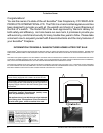
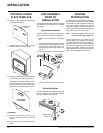
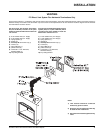
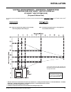
Back View of
Cover Plate
Pin Holes
Top Clip
INSTALLATION
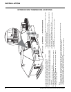
VENTING
INTRODUCTION
The P95-3 uses the "balanced fl ue" technology
Co-axial system. The inner liner vents products
of combustion to the outside while the outer
liner draws outside combustion air into the
combustion chamber thereby eliminating the
need to use heated room air for combustion and
losing warm room air up the chimney.
Note: These flue pipes must not be
connected to any other appliance.
The gas appliance and vent system must be
vented directly to the outside of the building,
and never be attached to a chimney serving a
separate solid fuel or gas burning appliance.
Each direct vent gas appliance must use it's own
separate vent system. Common vent systems
are prohibited (see "Simpson Dura-Vent Venting"
section for more details and exceptions).
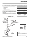
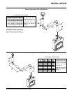
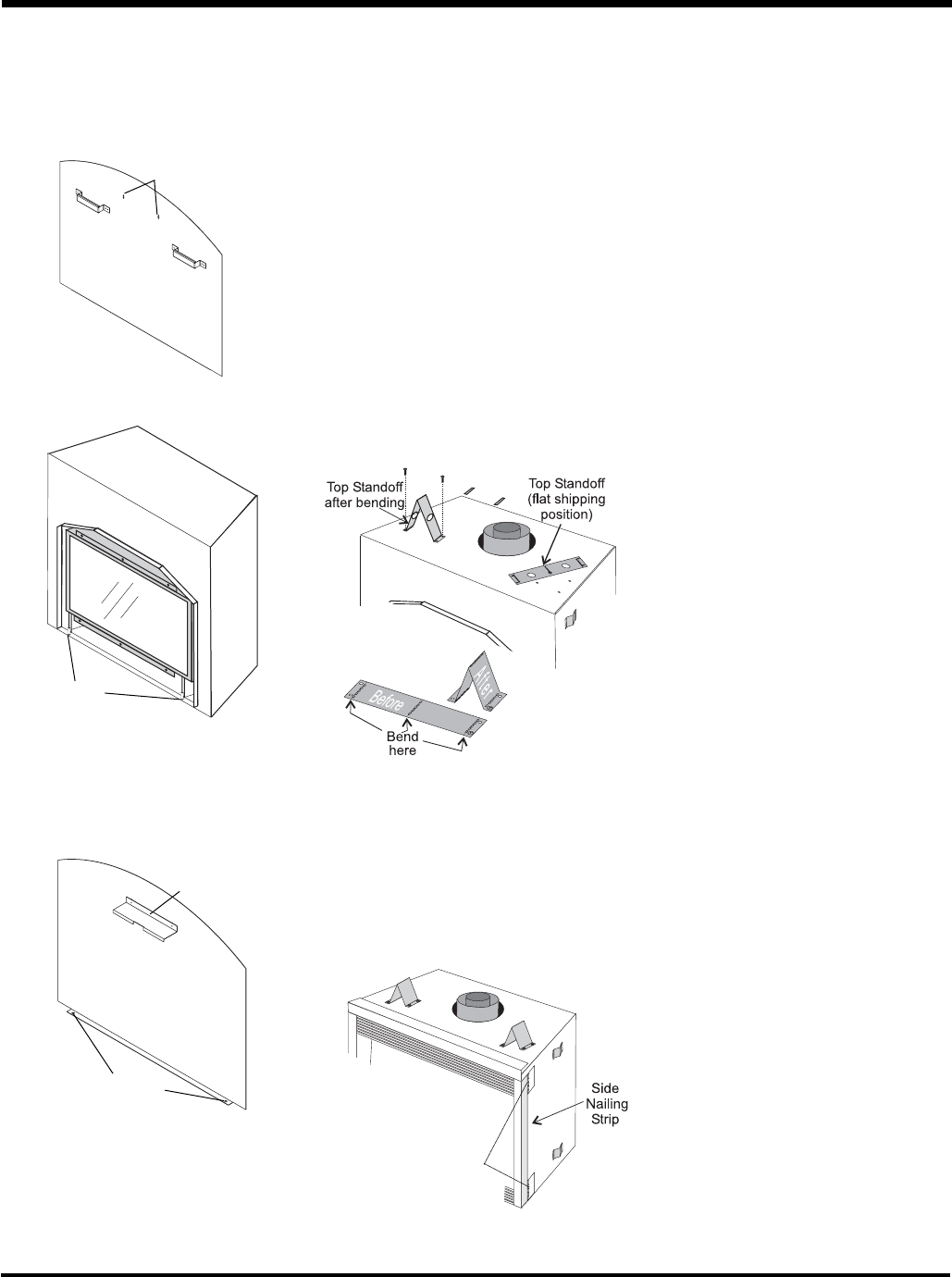
Side Nailing Strips
The side nailing strips come attached to the unit.
There are 2 plates, one on the top and bottom
that can be folded out as required.
Plates can be
folded out.
1) Ensure top clip screws are at top of oblong
holes before installation.
Pins
2) Position bottom of cover plate over pins
located at the bottom of the fi rebox.
Oblong Screw
Holes
3) Bring cover plate towards the unit and hook
top clip over and behind the glass frame.
The top clip may need to be adjusted. Loosen
the 2 screws that secure the top clip to let
the cover plate settle over and behind the
glass frame. Once settled tighten screws.
TO REMOVE:
1) Remove 2 screws that secure top clip.
Ensure to hold cover plate as it will fall
forward.
2) Pull out top clip that is still hooked onto
glass.
OPTIONAL COVER
PLATE TEMPLATE
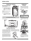
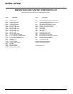
UNIT ASSEMBLY
PRIOR TO
INSTALLATION
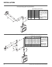
The 2 Top Standoffs must be correctly positioned
and attached to the top before unit is slipped
into position.
Top Standoff Assembly
The top standoffs are shipped in a fl at position
and must be folded into shape and attached.
1) Remove the standoffs from the fi replace
top.
2) Take each standoff and bend into the correct
shape. Bend up at the bend lines until the
screw holes in the standoff and the pre-
punched screw holes on the fi replace top
line up.
3) Attach the standoff securely to the top with 2
screws per standoff (on opposite corners).