


8
Gas Pressure Table
Gas Pressure Type Gas Pressure
Size 1-3 Inlet Pressure 7 in. w.c. – 14 in. w.c.
Size 4-5 Inlet Pressure 7 in. w.c. – 5 psi.
Max. Manifold Pressure - Natural Gas 5 in. w.c. maximum
Max. Manifold Pressure - Propane 2.5 in. w.c. maximum
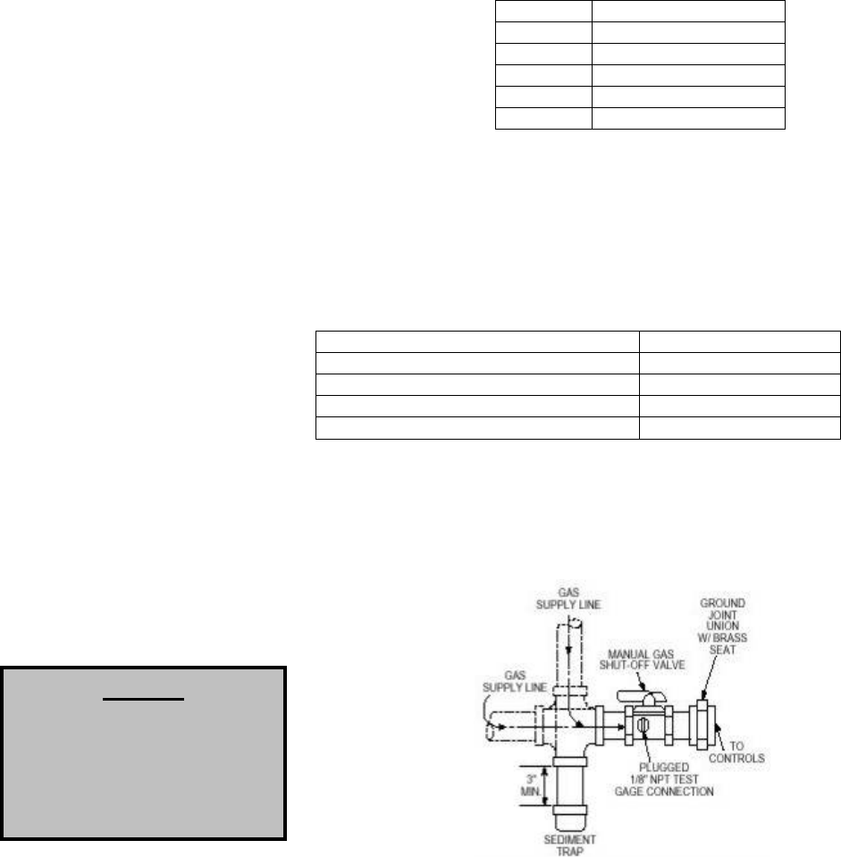
Gas Connection Sizes
Unit Size Gas Pipe Size (NPT)
Size 1 ¾”
Size 2 1”
Size 3 1”
Size 4 1-1/4”
Size 5 1-1/2”
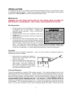
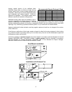
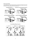
Gas Connection Diagram
Gas
Installation of gas piping must conform with local building codes, or in the absence of local codes, with the
National Fuel Gas Code, ANSI Z223.1 (NFPA 54) – latest edition. In Canada, installation must be in
accordance with CAN/CGA-B149.1 for natural gas units and CAN/CGA-B149.2 for propane units.
WARNING: INLET GAS PRESSURE MUST NOT EXCEED PRESSURE INDICATED
ON NAMEPLATE. SEE UNIT NAMEPLATE FOR PROPER GAS SUPPLY
PRESSURE AND GAS TYPE.
1. Always disconnect power before working on or near a heater. Lock and tag the disconnect
switch or breaker to prevent accidental power up.
2. Piping to the unit should conform with local and national requirements for type and volume of gas
handled, and pressure drop allowed in the line. Refer to the Gas Engineer’s Handbook for gas
line capacities.
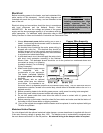
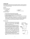
3. The incoming pipe near the heater should be sized to
match the connection on the outside of the unit. Unit inlet
sizes are shown in the table to the right. Avoid multiple
taps in the gas supply so the unit has a steady supply of
gas at all times.
4. Install a ground joint union with brass seat and a manual
shut-off valve external to the unit casing, as shown below,
adjacent to the unit for emergency shut-off and easy
servicing of controls.
5. Provide a sediment trap, as shown below, before each
unit and where low spots in the pipe line cannot be avoided.
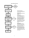
6. Blow out the gas line to remove debris before making connections. Purge line to remove air
before attempting to start unit. Purging of air from gas lines should be performed as described in
ANSI Z223.1-latest edition “National Fuel Gas Code”, or in Canada in CAN/CGA-B149.
7. All field gas piping must be pressure/leak tested prior to unit operation. Use a non-corrosive
bubble forming solution or equivalent
for leak testing. The heater and its
individual shut-off valve must be
disconnected from the gas supply
piping system during any pressure
testing of that system at test
pressures in excess of ½ psi. The
heater must be isolated from the gas
supply piping system by closing its
individual manual shutoff valve
during any pressure testing of the gas supply piping system at test pressures equal to or less
than ½ psi.
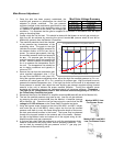
8. This unit requires a constant 7 in. w.c. minimum
natural gas supply, when the unit is operating at
maximum gas flow. If the gas supply exceeds 14 in.
w.c. (5 psi. for sizes 4-5 housings) it will damage the
internal valve components, and if it is below 7 in.
w.c., the heater may not perform to specifications.
NOTICE
Refer to the heater rating
plate for determining the
minimum gas supply
pressure for obtaining the
maximum gas capacity for
which this heater is specified.