


14
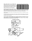
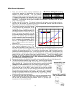
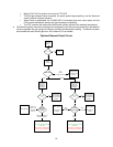
Maximum RPM and HP Chart
Blower Size Maximum RPM Maximum HP
10” 1800 2
12” 1500 3
15” 1400 5
18” 1200 5
20” 1000 10
25” 900 20
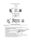
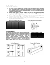
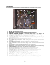
Pulley Adjustment Illustration
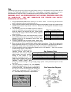
Pulley Setscrew Torque
Thread Size Torque (IN/Lb)
No. 10 (bushing) 32
1/4” (bushing) 72
5/16” 130
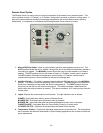
Final Start Up Procedure
1. With the air and burner systems in full operation and all ducts attached, measure the system
airflow. Motor sheave (pulley) is variable pitch, and allows for an increase or decrease of the fan
RPM to adjust the airflow, as shown in the illustration below. For your convenience, a RPM chart
is included in the following pages.
2. Once the proper airflow is achieved, measure and record the fan speed with a reliable
tachometer. Caution - Excessive speed will result in motor overloading or bearing failure.
Do not set fan RPMs higher than specified in the maximum RPM chart. See the
troubleshooting guide for more information.
3. Measure and record the voltage and amperage to the motor and compare with the motor
nameplate to determine if the motor is operating under safe load condition.
4. Once the rpm of the ventilator has been properly set, disconnect power and recheck belt tension
and pulley alignment as described below.
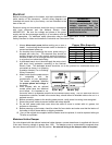
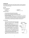
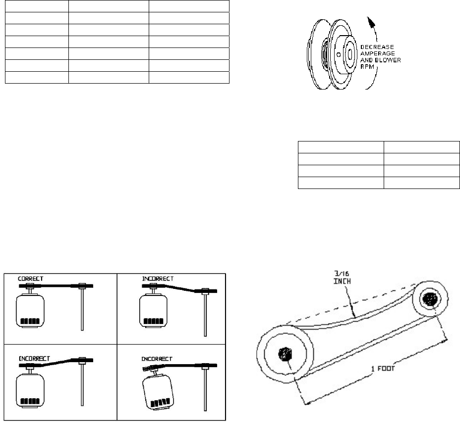
Pulley Adjustment
The adjustable motor pulley is factory set for the RPM specified.
Speed can be increased by closing or decreased by opening the
adjustable motor sheave. Two groove variable pitch pulleys must
be adjusted an equal number of turns open or closed. Any
increase in speed represents a substantial increase in
horsepower required by the unit. Motor amperage should always
be checked to avoid serious damage to the motor when the
speed is varied. Always torque setscrews according to the
setscrew torque chart.
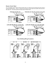
Pulley Alignment
Proper Belt Tension