


11
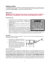
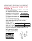
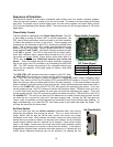
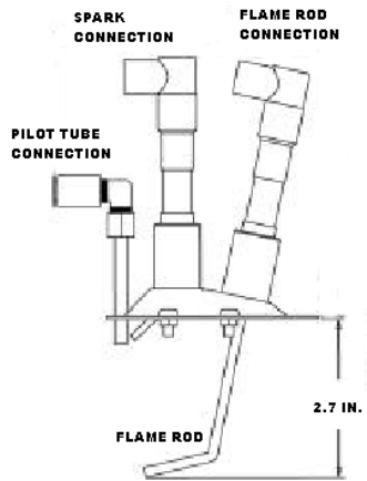
Pilot Assembly
OPERATION
Prior to starting up or operating the heater, check all fasteners for tightness. In particular, check the set
screw in the wheel hub, bearings and the fan sheaves (pulleys). With power and gas to the heater OFF or
prior to connecting ventilator to power, turn the fan wheel by hand to be sure it is not striking the inlet or
any obstacles. Re-center if necessary.
Start Up
Special Tools Required
• AC Voltage Meter
• Tachometer
• Standard Hand Tools
• Amperage Meter
• Manometer
• Differential Pressure Gauge
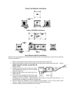
Start Up Procedure
1. Check all electrical connections for tightness and continuity.
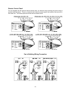
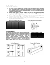
2. Check pulley alignment and belt tension as described below.
3. Inspect the condition of the intake damper and damper linkage, if provided.
4. Inspect the air-stream for obstructions and install intake filters if missing.
5. Compare the supplied motor voltage with the fan’s nameplate motor voltage. If this does not
match, correct the problem.
6. Start the fan up, by turning the external disconnect to the ON position, and shut it OFF
immediately to check rotation of the wheel with the directional arrow on the blower scroll.
Reversed rotation will result in poor air performance, motor overloading and possible burnout.
For units equipped with a single-phase motor check the motor wiring diagram to change rotation.
For 3-phase motors, any two power leads can be interchanged to reverse motor direction.
7. When the fan is started up, observe the operation and check for any unusual noises.
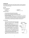
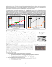
Pilot Adjustment
1. Restart the fan and check the gas supply pressure at the inlet
gas tap upstream of all electronic valves. The inlet pressure
should be 7 in. - 14 in. w.c. ( 7 in. w.c. – 5 psi on Size 4-5
heaters). If the inlet pressure is too high, install an additional
pressure regulator external to the unit.
2. Open the field installed manual gas shut-off valve and the
manual main gas valve on the combination gas control valve.
3. Call for heat with the intake air thermostat (turn set-point to
temperature above outside air) and allow the pilot to light. If the
pilot does not light, purge the pilot line. If air purging is
required, disconnect the pilot line at the outlet of the pilot valve.
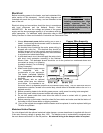
4. Check the pilot flame voltage at the Flame Safety Control
interface test jacks. A weak pilot flame can be caused by low
gas pressure, or a dirty pilot orifice. To adjust the pilot flame,
remove the cap from the pilot adjustment screw on the
combination gas valve. Increase the pilot gas flow by turning
the screw counter-clockwise. Decrease the pilot gas flow by
turning the screw clockwise. The pilot DC voltage should read
12 VDC minimum and should typically be 15 VDC.
5. Once the pilot has been established, open the main manual gas
shut-off valve downstream of the electronic valves. Check to
make sure that the main gas valve opens, and gas flows to the
burner.