


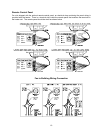

18
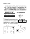
9 Begins Pilot Trial For Ignition and turns on PTFI LED
9 The pilot gas solenoid valve is opened, the spark igniter begins sparking, and the flamerod
sensor watches for flame initiation
9 When flame is established, the FLAME LED is illuminated and main valve opens and the
FSC powers the Maxitrol system and gas flow begins modulating
9 The FSC monitors the flame while the Maxitrol system adjusts to the selected temperature
• The Maxitrol system checks the discharge air temperature (and the room temperature for the Maxitrol
44) and regulates the gas going to the burner to satisfy the temperature setting. The Maxitrol system
will modulate the main burner gas from 100% down to 5% as needed.
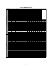
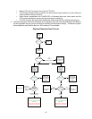
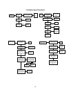
Optional Remote Panel Circuit
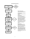
Power
Supply From
Heater
"Power" Light
On
Off
No Power to
Panel
Panel is
Powered
Blower Switch
Nothing Happens
No Power is Sent
to Heater
Power is Sent to
Heater to Open
Damper (if
provided) and
Start Blower
"Off"
Position
(3-Position Panels Only)
"Manual"
"Blower On"
Light
Damper is not
Open or Freeze-
Stat has Detected
Low Temperature
Operation
On
Off
Temperature
Control Switch
Blower Operates
Heat Does not
Operate
"Vent"
Position
"Heat"
Position
Heat Circuit is Energized
"Burner On" Light Illuminates with
proper flame.
"Flame Failure" Light illuminates
if proper flame is not established
Blower Operates
Cooling Circuit is
Energized
"Cool"
Position
(if provided)
Power is Sent to
Heater to Open
Damper (if
provided) and
Start Blower
"Blower On"
Light
Damper is not
Open or Freeze-
Stat has Detected
Low Temperature
Operation
On
Off
Intake Air
Thermstat is
Powered
Intake Air is Cooler Than
Thermostat Set-Point
Nothing Happens
Intake Air is
Warmer Than
Thermostat
Set-Point
"Auto"
Heat Circuit is Energized
"Burner On" Light Illuminates with
proper flame.
"Flame Failure" Light illuminates
if proper flame is not established