


12
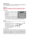
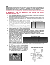
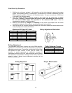
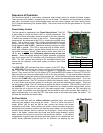
Maxitrol M511 and M611
Low Fire Bypass Screw
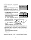
Mod Valve Voltage Summary
Volts DC Firing Mode
0 to 5 VDC Low Fire
5 to 15 VDC Modulation
15 to 20 VDC High Fire
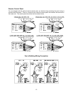
Maxitrol MR212 Low
Fire Bypass Screw
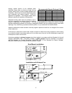
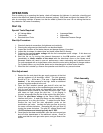
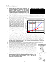
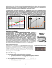
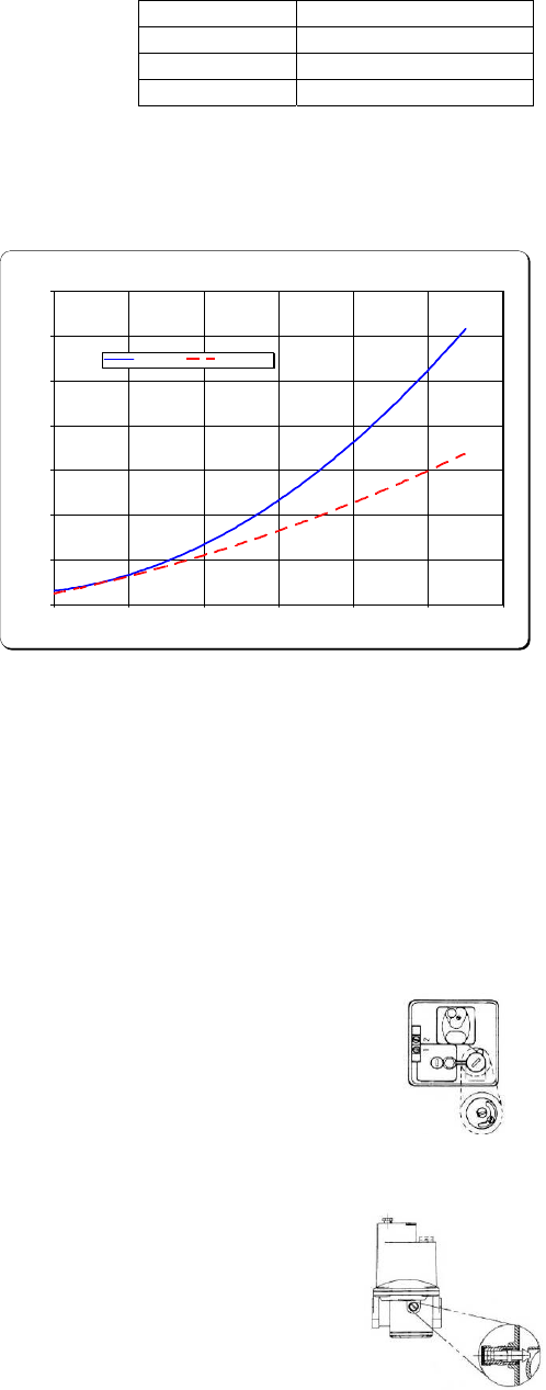
Average Manifold Pressure vs. Firing Rate/Ft. of Burner
-1.00
0.00
1.00
2.00
3.00
4.00
5.00
6.00
0 100000 200000 300000 400000 500000 600000
Firing Rate (BTU/Hr/Ft. of Burner)
Manifold Pressure (in. w.c.)
Natural Gas Propane Gas
Main Burner Adjustment
1. Once the pilot has been properly established, the
manifold gas pressure or temperature rise should be
adjusted to jobsite conditions. The gas pressure
regulator (integral to the combination gas control on size
1-3 heaters and located in the modulating valve on size
4-5 heaters) is adjusted at the factory for average gas
conditions. It is important that the gas be supplied to the burner in accordance with the input
rating on the rating plate.
2. Create a high fire call for heat. This should be done with the blower on and all gas controls on.
High fire can be achieved by removing the wire at terminal #4 (remove wires #2 and #4 for
Maxitrol 44 systems) from the Maxitrol 14 amplifier.
3. The manifold pressure should be checked
at the pressure tap downstream of the
modulating valve. The graph to the right
indicates the proper manifold pressure for
the desired amount of BTUs per foot of
burner. For natural gas systems, the high
fire manifold pressure should not exceed 5
in. w.c. For propane gas, the high fire
manifold pressure should not exceed 2.5
in. w.c. Another method of checking high
fire is to measure the temperature rise of
the unit. The temperature rise should be
set to design conditions and typically is
minimum 70°F.
4. Remove the cap from the combination gas
valve regulator adjustment (size 1-3) or
the cap from the MR212 valve (size 4-5).
Using the regulator pressure adjusting screw, adjust the high fire manifold pressure to 5 in. w.c.
maximum for natural gas and 2.5 in. w.c. maximum for propane gas. High fire should be set to
generate the desired temperature rise. If the high fire screw is at the end of its adjustment and
more pressure is needed, then adjust the main building gas pressure regulator spring (located
external to the unit) to achieve the proper manifold pressure. Turning the regulator screw
clockwise will increase pressure and counter-clockwise will decrease pressure. Remember -
The high fire DC voltage should read 12 VDC minimum and should typically be 15 VDC on
the Flame Safety Controller test jacks.
5. Reconnect the wire on the Maxitrol 14 amplifier at terminal #4 (wires #2 and #4 for Maxitrol 44).
6. The low fire manifold pressure must now be set. Low fire can be achieved
by removing the wire at terminal #5 from the Maxitrol 14 amplifier (remove
#8 for Maxitrol 44). Check the low fire flame signal to ensure that the DC
voltage is 12 VDC minimum on the Flame Safety Controller test jacks.
7. Using the bypass screw (located on the side of the M511 and M611 valves,
and under the cap of the MR212 valve), adjust low the low fire manifold
pressure until there is a very thin flame along the entire length of the burner.
No dark spots should be seen in the burner. The burner may be observed
through the view-port located on the external wall of the heater. Replace
the cap to the Maxitrol valve and restore all of the original wiring on the
Maxitrol amplifier and gas components.
8. A final gas leak check shall be performed to verify the gas-tightness of the
heater’s components and piping under normal operating conditions. This
can be done by measuring the gas pressure at the ¼” gas plug just
downstream of the modulating valve.