


035-18496-000-C-1102
Unitary Products Group 7
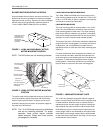
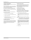
BLOWER MOTOR MOUNTING LOCATIONS
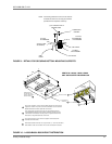
Units are shipped from the factory less motor and drives. The
blower motor and drive packages are ordered and shipped
separately for field mounting. However, the units are shipped
with the motor mounting assembly installed as shown in
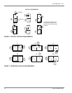
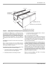
1 for the LA300, LB360, LB480 and 2 for the LB600.
NOTE: The 5HP motors are not inherently protected.
The motors used with the evaporator blower are 3-phase and
can drive the blower wheels from either end of the blower
section. Reversing the direction of rotation can be accom-
plished by changing the connection of the power supply wir-
ing at the motor terminal box.
NOTE: The 7.5-15 HP blower motors have solid bases
and are not inherently protected. For proper
operation, these motors require overload
heater elements. Please see curent product
price pages for overloads.
LA300/LB360/LB480 MOTOR MOUNTING
The LA300, LB360 and LB480 ship from the factory with a
motor mounting adapter plate for use with the 7.5 and 10 HP
motors. If a 5 HP motor is used, the adapter is not necessary
and should be removed and discarded.
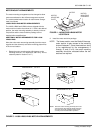
LB600 MOTOR MOUNTING
The motor mounting plate will accommodate a 10 or 15 HP
motor. One set of boltholes is provided on each end of the
motor mounting plate for either motor. The motor mounting
plate can be raised or lowered to any position on the adjust-
ment screws to adjust the belt tension for the various pulley
settings to cover the complete range of blower speeds.
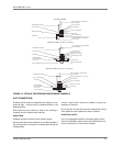
The physical size of the 15 HP motor reduces the adjustment
range of the motor mounting plate. To maximize this amount
of adjustment, one set of boltholes is provided near the
adjustment screws on each end of the motor mounting plate
(refer to 4).
For some motor/blower wheel arrangements, however, the
motor cannot be mounted in these bolt holes because the
motor terminal box would interfere with one of the blower sec-
tion panels. To make these motor/blower wheel arrange-
ments possible, a second set of boltholes is provided near
the pivot bolts on each end of the motor mounting plate.
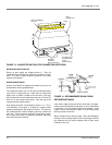
The 15 HP drive package requires two different lengths of
belts to vary the blower wheel RPM over the complete range
of rated conditions. When the motor is mounted near the
adjustment screws, the two lengths of belt are interchange-
able except for the higher and lower limits of blower wheel
RPM. When the motor is mounted near the pivot bolts, the
shorter length of belt is recommended for the higher blower
wheel Rpm's and the longer length of belt is recommended
for the lower blower wheel Rpm's. See Page 7 for the recom-
mended blower motor locations.
FIGURE 1 - LA300 AN LB360/LB480 FACTORY
MOTOR MOUNTING POSITION
FIGURE 2 - LB600 FACTORY MOTOR MOUNTING
POSITION
MOTOR MOUNTING
CHANNELS AND
MOUNTING PLATE
ARE ALWAYS
SHIPPED IN THIS
LOCATION.
A lte rn a tiv e P o s itio n
1 F o r P iv o t B o lts
Alternate
Position 3
F o r P iv o t B o lts
A lte rn a tiv e P o s itio n
2 F o r P iv o t B o lts
Adjustment
S cre w (2 )
M otor M ounting Plate
(Standard Location
a
s Shipped)
P iv o t B o lt (2 )
FIGURE 3 - LB600 MOTOR MOUNT PLATE
10 HP
Adjustment
Screw Holes
15 HP
15 HP
15 HP
15 HP
10 HP
15 HP
15 HP