


035-18496-000-C-1102
Unitary Products Group 25
To check the supply air CFM after the initial balanc-
ing has been completed:
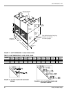
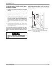
1. Drill two (2) 5/16-inch holes in the side panel as shown in
Figure 24.
2. Insert at least 8 inches of 1/4 inch tubing into each of
these holes for sufficient penetration into the airflow on
both sides of the evaporator coil.
3. Using an inclined manometer, determine the pressure
drop across a dry evaporator coil. Since the moisture on
an evaporator coil may vary greatly, measuring the pres-
sure drop across the wet coil under field conditions
would be inaccurate. To assure a dry coil, the refrigerant
system should be de-activated while the test is being
run.
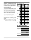
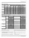
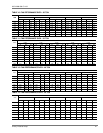
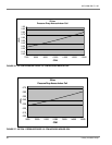
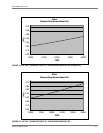
4. Knowing the pressure drop across a dry coil, the actual
CFM through the unit can be determined from the curves
shown in Figures 25-28.
If the CFM is above or below the specified value, the supply
air motor pulley may have to be readjusted. After one hour of
operation, check the belt and pulleys for tightness and align-
ment.
After readings have been obtained, remove the tubes and
seal up the drilled holes in the side panel. 5/16 inch dot plugs
(P/N 029-12880) are available through normal York parts
ordering procedures.
Failure to properly adjust the total system air
quantity can result in extensive blower dam-
age.
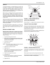
FIGURE 25 - HOLE LOCATION FOR PRESSURE
DROP READING
5/16"
HOLE
5/16"
HOLE
"
7"
25"
14"
EVAPORATOR
COIL
FILTERS
COIL SECTION
22