


035-18496-000-C-1102
Unitary Products Group 17
Suitable hangers, brackets or clamps should support the
refrigerant lines.
Braze all copper-to-copper joints with Silfos-5 or equivalent
brazing material. Do not use soft solder.
Never braze or solder the liquid and suction lines together.
The complete suction line should be insulated with no less
than ½" Armaflex or equivalent.
If it is desirable to tape or wire the liquid and suctions lines
together for support purposes, they must be completely insu-
latedfromeachother.
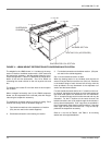
EVAPORATOR SECTION PIPING
The units are shipped with a holding charge of R-22. The
connections are terminated with a copper disc brazed over
the ends.
Before starting installation of the mains, be sure the unit has
not developed a leak in transit by connecting a pressure
gauge to the service access port. If pressure still exits, the
circuit may be considered leak free. If pressure does not
exist, the unit must be evacuated along with the field installed
refrigerant piping.
NOTE: To minimize the possibility of system failure
due to dirt and moisture, a filter-drier must be
installed in each liquid line as close to the
evaporator as possible. Filter-driers are not
supplied with the evaporator blowers. They
are supplied with the matching HA/HB series
condensing units.
The temperature required to make or break a brazed joint is
sufficiently high to cause oxidation of the copper unless an
inert atmosphere is provided.
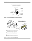
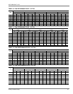
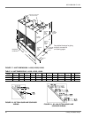
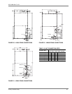
The liquid, suction and drain connections inside the unit must
be piped to the outside. Refer to 17 and 23 for unit dimen-
sions or the locations and the dimensions of the access
openings in the unit panel.
Remove the evaporator holding charge and any caps or discs
on the liquid and suction connections that will not permit a
free flow of nitrogen.
Connect a supply of dry nitrogen through a reducing regulator
to an access valve or charging tail. Choose a procedure that
will allow nitrogen to flow continuously through the system
and reach all joints to be brazed.
Begin the refrigerant main piping by installing the liquid line
from the condensing unit to the evaporator liquid connection,
maintaining a flow of nitrogen during all brazing operations.
The filter drier and sight glass must be located in this line,
close to the evaporator. Make the suction line connection at
the evaporator and run the line to the condensing unit.
After puncturing the sealing caps with a small drill bit,
unbraze the condensing unit suction disc and connect the
line. Maintainaflowofnitrogenthroughtheliquidlinetothe
evaporator, through the evaporator, back to the condensing
unit and out the suction connection and service port.
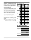
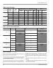
NOTE: Size the suction line outside the evaporator
casing per the line sizing information provided
in the condensing unit instruction form 035-
18499-000.
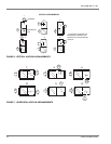
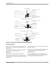
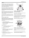
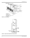
EXPANSION VALVE BULB INSTALLATION
LA300
The bulbs for the thermal expansion valve on the blower units
are not factory-installed in its final location; it's only tempo-
rarily taped for shipment. They must be fastened in a 4
o'clock and 8 o'clock position to the common suction line out
of the evaporator coil after piping connections are made. Use
the bulb clamps from the bag taped to the suction connection
inside the blower unit.
LB360/LB480/LB600
The bulbs for the thermal expansion valve on the blower units
are not factory-installed in its final location; it's only tempo-
rarily taped for shipment. The bulbs for system one must be
fastened in a 4 o'clock and 8 o'clock position to the system
one suction line of system one leaving the evaporator coil
after piping connections are made. Repeat the procedure for
system two, locating the bulbs in a 4 o'clock and 8 o'clock
position to the system two suction line. Use the bulb clamps
from the bag taped to the suction connection inside the
blower unit.
NOTE: Ensure the TXV bulbs are not crossed
between systems. Undesirable performance
and possible compressor damage may occur.
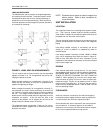
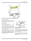
LIQUID LINE SOLENOIDS
The unit is shipped with factory installed, normally closed, liq-
uid line solenoid valves. When the solenoid coil is energized
with a 24-volt signal, the valve will open.
During brazing operations, the valves should be placed in the
OPEN position by removing the stem cap with a 9/16”
wrench, then rotating the exposed valve stem inward
(CLOCKWISE), approximately 10-12 full turns (from the fully
CLOSED position), using a 4” adjustable wrench.
The valve stems should be returned to the CLOSED
(COUNTER-CLOCKWISE) position prior to the unit’sopera-
tion. The “Pump-out” procedure is detailed in the following
section.
The sequence of operation applies to the HA/HB condensing
units and LA/LB air handlers when applied as a matched sys-
tem. Non-matched systems will have to be field wired to oper-
ate in a similar fashion as described on page 19.
NOTE: See Liquid Line Solenoid Wiring on page 22.