


035-18496-000-C-1102
Unitary Products Group 11
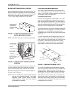
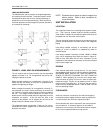
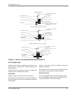
LB600 AIR DISCHARGE
The LB600 blower and coil section are shipped separately
and must be joined in the field. The blower section can be
mounted either above the coil for a vertical positioning or
beside the coil for horizontal positioning. Both vertical and
horizontal positions can be arranged for upward, downward,
or horizontal air discharge.
The coil section and the blower section may be assembled
together as shown in 8. All arrangements may be by rear-
ranging the panels as shown.
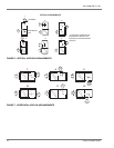
When arranged vertically (8, arrangements 1 through 3), the
LB600 can be set directly on any floor or platform that is
capable of supporting its weight.
When arranged horizontally (8, arrangements 4 through 7),
the evaporator coil section can be set directly on the floor, but
a 9" support is required under the blower section to stabilize
the unit. The support should extend the full width of the
blower section and be located under the edge away from the
evaporator coil section. If the unit does not have to be
secured to the platform, the 9" support will not have to be
bolted to either the blower section or the floor.
The evaporator blower arrangement 7 shown in 8 is not rec-
ommended for bottom support due to interference with the
ductwork connection.
NOTE: Ductwork should never be used to support the
blower section. Refer to duct connection for
more information
UNIT INSTALLATION
LOCATION
The evaporator blowers are not designed for outdoor installa-
tion. They must be located inside the building structure,
either inside or outside the conditioned space where they are
protected from rain and other such moisture.
The unit should be located as close to the condensing unit as
practical and positioned to minimize bends in the refrigerant
piping.
Units being installed vertically or horizontally can be set
directly on a floor or platform, or supported by metal or
wooden beams.
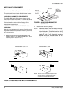
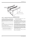
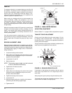
Units being installed horizontally (LA300, LB360 & LB480
only) can be suspended from above as shown in figure 12.
Refer to form 035-18501-000 for more information on the
installation of the suspension accessory and for the individual
load on each hanger rod.
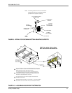
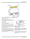
RIGGING
Caremustbetakenwhenmovingtheunit. Donotremove
any packaging until the unit is near the place of installation.
SPREADER BARS SHOULD BE USED BETWEEN THE
SLINGS TO PREVENT CRUSHING THE UNIT FRAME OR
PANELS. When preparing to move the unit, always deter-
mine the center of gravity of the unit in order to equally dis-
tribute the weight. Rig the unit by attaching chain or cable
slings around the bottom skid. A lift truck may be used to
raise a unit to a suspended location. Refer to Table 2 for the
total unit operating weight.
CLEARANCES
A 25-inch clearance is required on the end with the piping
connections and the supply air blower motor to properly ser-
vice and maintain the unit and to replace the filters.
Some clearance will also be required for the duct and power
wire connections. A clearance equal to the unit width is
required on one end of the unit if the blower shaft or evapora-
tor coil is to be replaced without moving the unit.
FIGURE 8 - LB600 AIRFLOW ARRANGEMENTS
1
3
2
6
54
7