


035-18496-000-C-1102
18 UnitaryProductsGroup
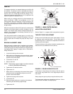
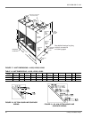
PUMP OUT
The pump out function is a standard feature on the 25 to 50
ton systems. The pump out circuit is activated each time the
first and third compressor stage is called for by the thermo-
stat. As such, it’sa“Pump Out On Start Up” design. A nor-
mally closed solenoid valve (POS1, 2, 3 or 4) is placed in the
liquid line, just prior to expansion valve.
When cooling is not being called for by the thermostat, the
pump out solenoid (POS) is not energized, so it’sinthe
closed position. When the Simplicity™ control receives a call
for cooling, it energizes a compressor. With the POS being
closed, it causes the pressure on the low side of the system
to begin falling.
When the low pressure switch (LPS) opens, the control board
energizes its on-board pump out relay, providing a 24 vac
output to an external relaly used to energized the pump out
solenoid. The refrigeration circuit being controlled is not in
normal operating mode.
If the low pressure switch is already open on a call for cool-
ing, the pump out relay is energized immediately. If the LPS
does not open after 5 minutes, the pump out relay is ener-
gized.
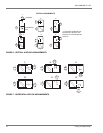
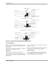
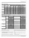
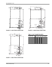
BEARING ALIGNMENT: LB600
Before the supply air blower drive is installed, turn the blower
assembly by hand several times. If it doesn't rotate freely, the
center bearing may have been knocked out of alignment dur-
ing shipping and/or rigging. To realign, refer to 15 and the fol-
lowing instructions:
1. Loosen the bearing collar set screw.
2. With a drift pin in the bearing collar removal hole, loosen
the bearing collar by tapping the drift pin in the direction
opposite to the shaft rotation.
3. Loosen bolts "A" and "B".
4. Remove the shim.
NOTE: The bearing support angle must be horizontal
to the unit and below the bearing.
5. Tighten bolts "B" without the shim.
6. Tighten bolts "A".
7. With a drift pin in the bearing collar removal hole, tighten
the bearing collar by tapping the drift pin once in the
direction of the shaft rotation.
8. Tighten the bearing collar set screw.
9. Loosen bolts "B"
10. Raise the blower shaft and re-install the shim between
the bearing and the bearing support angle.
11. Tighten bolts "B".
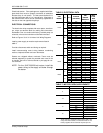
AIR SYSTEM ADJUSTMENT
Refer to Tables 7-11 on pages 19-20 to adjust the air system.
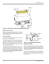
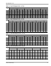
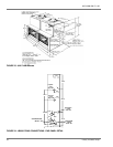
TWIN BELT DRIVE ADJUSTMENT
Check to see if both belts drive at the same speed. Do this
by making a mark across both belts. Turn the drive several
revolutions by hand. If mark has not separated, the belts are
traveling at the same speed.
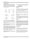
Twin groove blower motor pulleys should be installed with the
shaft set screw (A) towards the motor (see 16).
If necessary to align pulleys, the housing of the twin groove
motor pulley may extend 25% of its length beyond end of
motor shaft.
Always align twin groove pulleys using the stationary web.
The blower motor pulleys are adjustable by half turns. Select
required RPM from table 5 and adjust pulley.
FIGURE 15 - LB600 CENTER BEARING
FIGURE 16 - DOUBLE GROOVE PULLEY
SHAFT
ROTATION
BEARING COLLAR
SET SCREW
BEARING
COLLAR
BLOWER
SHAFT
BOLT "B" BOLT "B"
BEARING
BEARING
COLLAR
REMOVAL
HOLE
BEARING SUPPORT ANGLE
SHIM
BOLT "A"
A
B
B
C
D
E
STATIONARY WEB
C