7
ENVISION SERIES INSTALLATION MANUAL
Dual Fuel Systems
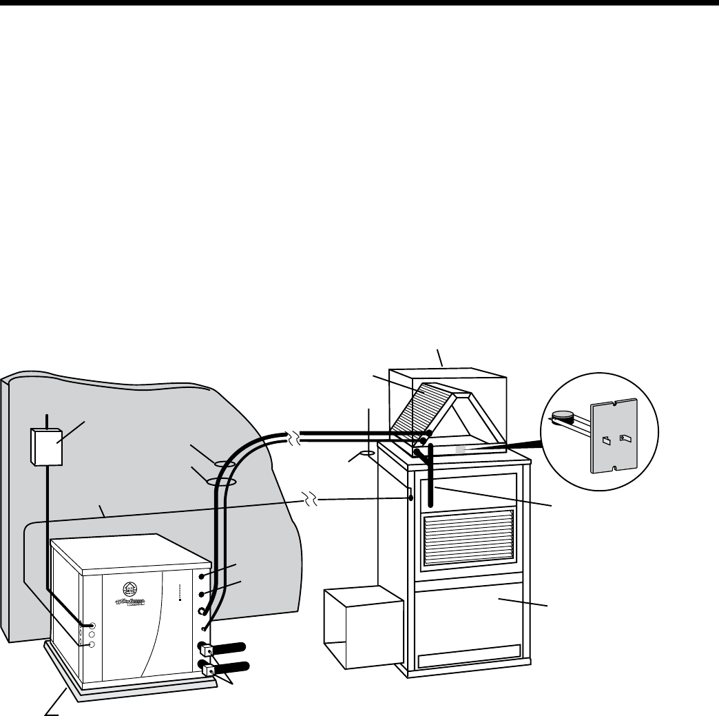
Envision units can be connected to fossil fuel furnaces that include an A-coil or slab coil. Dual fuel installations utilize the
Envision heat pump for heating until the point that auxiliary heat is called for on the thermostat. At that point, the furnace
will be enabled and the heat pump will be disabled. The Envision heat pump provides air conditioning through the furnace’s
refrigerant coils.
Refer to the furnace manufacturer’s installation manual for the furnace installation, wiring and coil insertion. A
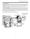
WaterFurnace Dual Fuel thermostat, a eld-installed DPST relay or dual capacity auxiliary heat relay is required. See Figure
2 for typical Dual Fuel application.
In add-on Envision Split applications, the coil should be located in the supply side of the furnace to avoid condensation
damage to the furnace heat exchanger. A high temperature limit should be installed upstream of the coil to de-energize the
compressor whenever the furnace is operating. Without this switch, the Envision Split will trip out on high pressure. A dual
fuel thermostat can remove the Y1 and Y2 calls when a W call is energized to allow gas furnace backup on an Envision Split
application. Refer to thermostat wiring on page 15 for details.
Disconnect
Thermostat
Wire From Furnace
Vibration Absorbing Pad or Air Pad
P/T Plugs
Wire To
Thermostat
Up-Flow
Fossil Fuel
Furnace
Condensate
Drain
(must be trapped)
"A" or
Slab Coil
Supply Duct
Air Temperature Limit Switch -
to prevent compressor operation
when entering air is greater than
90°F.
Water Out
Water In
Lineset To Air Handler
Insulated
Suction Line
DHW In
Return
Duct
DHW Out
Figure 2: Typical Split System Heat Pump Coil Add-On Fossil Fuel Furnace


