


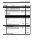
17
ENVISION SERIES INSTALLATION MANUAL
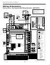
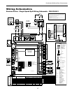
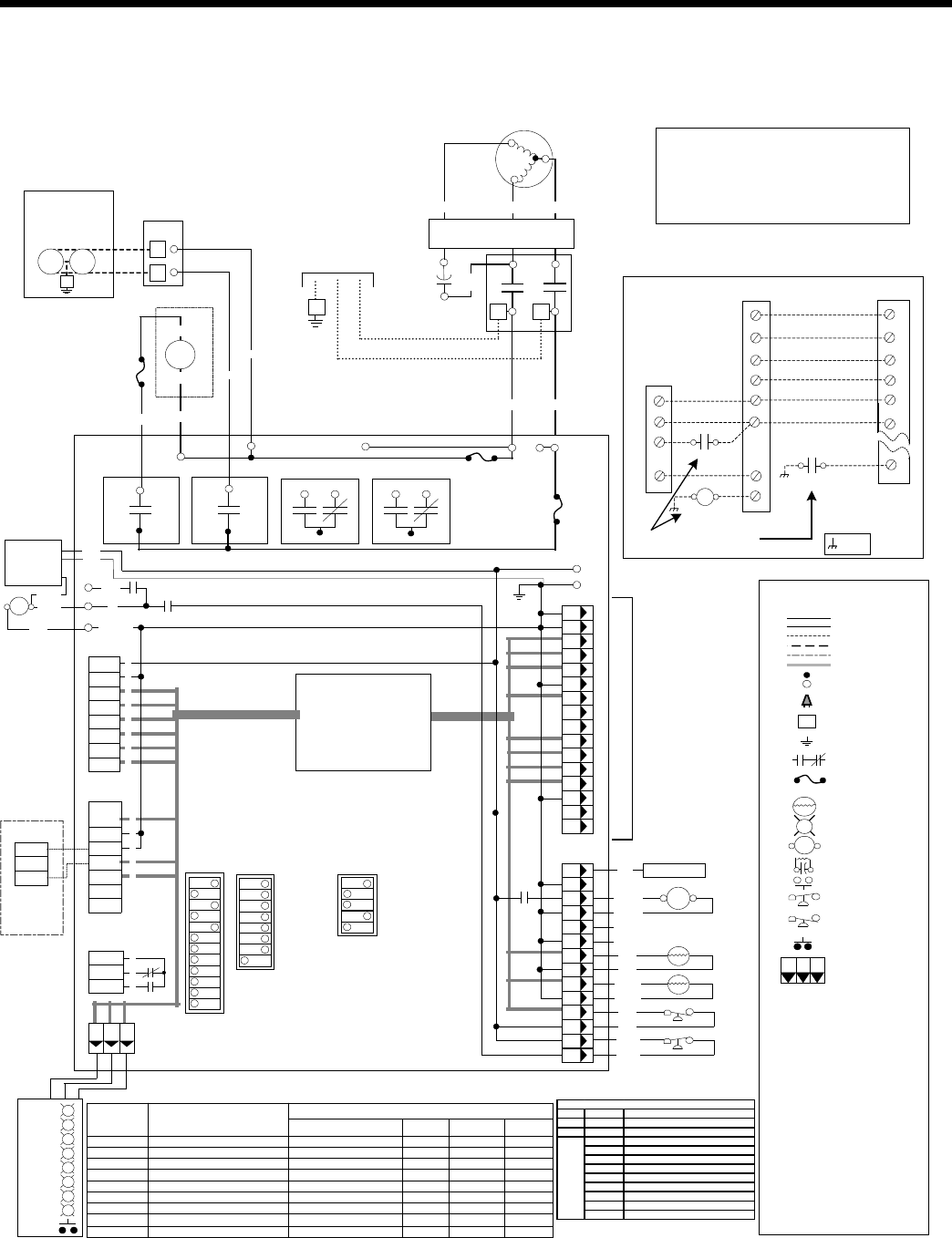
Wiring Schematics
Envision Series - Single Speed Split Wiring Schematic - 208-230/60/1
HWL
HP
LP
WCL
97P774-30 3/9/07
StatusLEDPCB
SW4
R
R
R
R
R
G
Y
R
T
T
240VL2
240VL1
240VL2
P6
Premier 2
Microprocessor
Logic Control
(DC Voltage)
P1
Fused L2
R
C
CC-GND
NO
CR2
COM
F1-10A240V
Fused L2
NO
CR1
COM
1
2
3
4
5
6
7
8
1
2
3
P4
Pink
Black
Blue
Orange
Orange
Pink
Yellow
Yellow
1
2
3C
P2
Down
C
1
2
3
4
5
6
7
Shut
SL1In
Not
SL1Out
Used
NOTE1
AccCom
AccNC
AccNO
1
2
3
P3
1 2 3
MainLogicPCB
F1-10A
240V
Tan
6
5
4
8
7
P5
12
1
2
9
10
3
4
9
11
2
10
8
1
12
5
3
13
14
15
16
11
G
W
O
R
C
Y1
Y2
LO
On
SW1
1
2
3
4
5
6
7
8
9
10
11
12
ECM2
AirFlow
Settings
Black
Blue
14
13
6
7
CC
NO
NC
CR4 COM
NO
NC
CR3 COM
RV
CCHI
NotUsed
NotUsed
On
SW3
On
SW2
1
2
3
4
5
6
7
8
NoHtg3/Htg3
Dehum/Norm
Fan/Comp
Loop/Well
Test/Norm
Outputs/Norm
Inputs/ Norm
2Speed/1Speed
Normal/Finishon2
nd
(Note2)
NoRPM/RPM
ElectricHeat /Normal
Envision/ESeriesorPremier
1
2
3
4
5
PulseL/ConstantL(NOTE4)
FieldSelectionDips -#1On,#6On,#7On
DrainpanoverflowLockout
FPthermistor(loop<15°F,well<30°F)Lockout
HighPressure>600PSILockout
Low Pressure<40PSILockout
ECM2RPM<100rpmLockout
Microprocessormalfunction*
HWLthermistor>130°F
DHWpumpswitchoff
Drain
WaterFlow
HighPress
LowPress/Comp
AirFlow
Status
DHWLimit
DHWoff
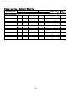
LED NormalDisplayMode
#1Off,#6On,#7On
Drainpanoverflow
FPthermistor(loop<15°F,well<30°F)
HighPressure>600PSI
Low Pressure<40PSI
ECM2RPM<100rpm
NotUsed
HWLthermistor>130°F
DHWpumpswitchoff
CurrentFaultStatus
#6Off,#7On
Y1
Y2
O
G
W
SL1
SL2
--
Inputs
#6On,#7Off
CompressorLo
CompressorHi
RV
FAN
DHWPump
LoopPump1
LoopPump2
--
Outputs
#6Off,#7Off
BlowerLo
BlowerMed
BlowerHi
AuxHeat#1
AuxHeat#2
AuxHeat#3
AuxHeat#4
--
Outputs2
DiagnosticModes
*GreenLEDnotflashing
Notes:
1-24VAccessory relay(seeSW2-3fordescriptionofoperation)
4–SW2-8mustbeintheOFFpositionforpulsed“L”lockoutsignalandintheONpositionforconstant
“L”lockoutsignal.
2–ThisSwitchallowstheunittodownstagewiththet-statwhenOFFandfinishonsecondstagewhen
ON. Finishsecondstagereducesstagechanginginrecipdualcapacitycompressorsandshould
beONforunzonedDualCapE-Seri esorPremier2speedunits.
Thermistor
Light emittingdiode-Green
Relaycoil
Capacitorw/bleedresistor
Switch-Condensateoverflow
Switch-Highpressure
Switch-Lowpressure
Switch-Hot WaterOn/Off
Polarizedconnector
FactoryLowvoltagewiring
FactoryLinevoltagewiring
Fieldlowvoltagewiring
Fieldlinevoltagewiring
Optionalblock
DCVoltagePCBtraces
Internaljunction
Quickconnect terminal
Wirenut
Fieldwirelug
Ground
Fuse
CC-
CO-
CR1-
CR2-
CR3-
CR4-
F1andF2-
WCL-
HE-
HP-
LP-
PB1,PB2-
PS-
RV-
SW1-
SW2-
SW3-
SW4-
TS-
CompressorContactor
Condensateoverflowsensor
DHWpumprelay
Looppumprelay
Fuses
WaterCoilLimitSensor
Heaterelement
Highpressureswitch
Low pressureswitch
Powerblocks
Powerstrip
ReversingValvecoil
DIPpackage12position
DIPpackage8position
DIPpackage5position
Hotwaterpumpenableswitch
Thermallimitswitch
Legend
RelayContacts-
N.O.,N.C.
G
T
132
P
L1
PSCFanSpeedRelay
PSCFanPowerRelay
ER1toER4- Auxheatstagerelays
HWL-
Hotwaterlimitsensor
SC-
StartContactor
StartRelay
SR-
CS- CompressorSolenoid**DCCoil**
CA-
ComfortAlert
Y1
Y2
O
R
C
L
C
R
FossilFuel
Furnace
Thermostat
24VAC
Common Common
24VAC
FaultSignal
ReversingValve
2ndStageCompressor
1stStageCompressor
Y1
Y2
O
R
C
LO
EZSplit
G
G
Fan
W
W
AuxiliaryHeatRelay
DuelFuelWiringDiagram
UsingFieldInstalledRelay
Note: FieldinstalledDPSTdualf u elrelay
(Requiredfordualfuelinstallation)
AuxiliaryHeatRelay
P2
P1
Shut
Auxiliary
HeatRelay
Down
=chassis
LED FlashCodeDescription
Green Solid ModuleHasPower
Red Solid Y1PresentButCompressorNotRunning
Code1 LongRunTime
Code2 SystemPressureTrip
Code3 ShortCycling
Code4 LockedRotor
Code5 OpenCircuit
Code6 OpenStartCircuit
Code7 OpenRunCircuit
Code8 WeldedContactor
Code9 LowVoltage
Yellow
ComfortAlertStatus
NOT U
S
E
D
5-DHWpumponlyinmodelswithhotwatergenerationoption.
NOTE5
DHW
Pump
Blu
3A
Fuse
Pink
Blu(17)
Ext Pump
1/2 hp Total
208-230/60/1
Pump Pump
G
2
1
PB1
1
2
Yel(8)
Pink(13)
Unit Power
208-230/60/1
G
L2 L1
CC
C
S
R
Run
Capacitor
Red Black
Blue
Tan
(16)
Comfort Alert
CC
Blk(1)
Violet(2)
Comfort
Alert
R
Y
C
Violet(3)
Blk(5)
Yel(6)
L
ComfortAlert
NOTE3
Brn(15)
Org(14)
Gry(9)
C
NOTE6
SL1In
SL1Out
Optional
RemoteUnit
Without
LoopPump
6-Connectionofremoteunitthatdoesnothavealooppumpforslaveoperation .
3-ComfortAlertfaultoutputtoPremierControlBoard