


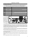
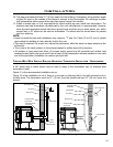
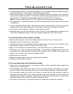
4. Connect a tee or 90° degree elbow to the
exhaust pipe.
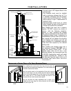
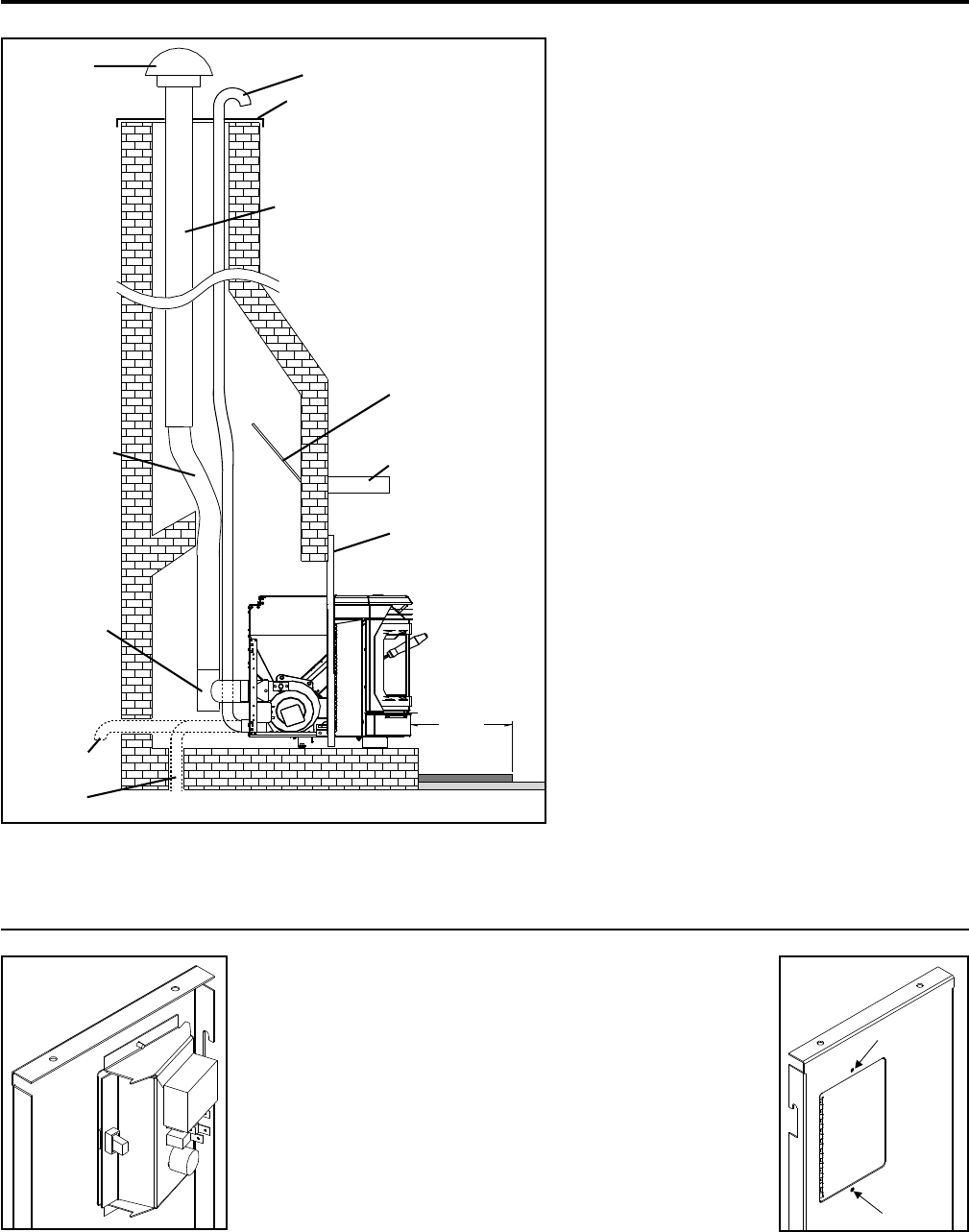
5. This fireplace insert must be installed
with a continuous chimney liner of 3” or
4” diameter extending from the fireplace
insert to the top of the chimney. The liner
must conform to type 3 requirements of
CAN/ULC S635.
6. (Recommended) Install fresh air intake
either through the back of the fireplace or
through the positive flue connector.
When installing the insert into a masonry
fireplace, DO NOT remove any bricks or
masonry, with the following exception:
masonry or steel, including the damper
plate, may be removed from the smoke shelf
and adjacent damper frame, if necessary, to
accommodate a chimney liner. Do this only if
their removal will not weaken the structure
of the fireplace and chimney, and will not
reduce protection for combustible materials
to less than that required by the national
building code.
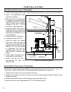
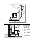
When installing the fireplace insert into a
zero clearance fireplace, DO NOT cut or
modify any factory firebox parts. If the
fireplace insert does not fit into a zero
clearance fireplace, we recommend you use
an ENVIRO freestanding model and install
as a hearth mounted unit. Install a 3” (76
mm) flex pipe from the stove to the top of
the chimney (see “HEARTH MOUNT INSTALLATION
- FREESTANDING:”).
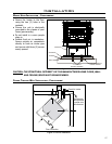
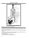
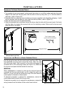
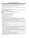
When installing the control panel into the surround panel, the
surround does not need to be assembled. The control board will
be found in behind the firebox.
Place the control panel on the backside of the right surround
panel so the hinge is on the outside and the top and bottom
holes on the control panel line up with those on the surround.
Attach using two (2) T-20 screws through the front of the
surround into the circuit board control panel.
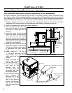
After the surround has been assembled and is ready to be
installed on the unit, plug the wiring harness into the control
panel (see Figure 28).
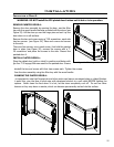
INSTALLATION OF CONTROL PANEL IN THE INSERT SURROUND PANELS:
Installation
Figure 27: Masonry fireplace installation.
Figure 28: Control Panel
Back.
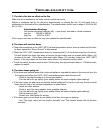
Figure 29: Control
Panel Cover.
23