


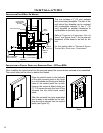
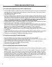
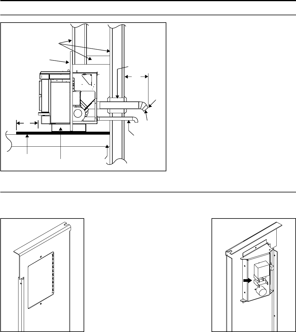
Non-combustible
floor protection.
Existing floor
(combustible)
6"
(15 cm)
3" (7.5 cm)
Pedestal
Wall
thimble
Fresh air
intake
Rodent
mesh cap
45°
elbow
12"
(30.5 cm)
Surround Panel
Combustible
materials and
structure
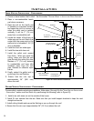
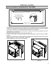
Installation
INSTALLATION FOR A BUILT-IN HEATER:
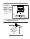
This unit includes a 3” (75 mm) pedestal
and surrounding faceplates. The part of the
unit behind the faceplate can be enclosed
with combustible material. It has 1” (25
mm) standoffs to establish clearances to
combustibles to the back, top and sides.
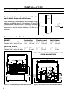
Refer to “CLEARANCES TO COMBUSTIBLES - BUILT-IN
HEATER“ and Figure 6 and 7 for the size and
placement of the alcove to be built for the
unit.
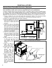
For the venting refer to “HORIZONTAL EXHAUST
THROUGH WALL INSTALLATION - FREESTANDING“.
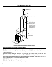
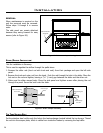
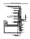
INSTALLATION OF CONTROL PANEL INTO SURROUND PANEL - FPI AND BIH:
When installing the control panel into the surround panel, the surround does not need to be assembled.
The control board will be found in behind the firebox.
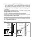
Figure 31: Control Panel Cover.
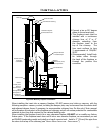
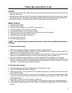
Figure 32: Control Panel Back
- Timer.
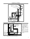
Figure 30: Built-in heater installation.
Place the control panel on the backside
of the right surround panel so the hinge
is on the outside and the top and bottom
holes on the control panel line up with
those on the surround. Attach using two
(2) T-20 screws through the front of the
surround into the circuit board control
panel.
After the surround has been assembled
and is ready to be installed on the unit,
plug the wiring harness into the control
panel (see Figure 32).
24