


Page 34 19400-3-0406
CAUTION: ALL WIRING SHOULD BE DONE BY A QUALIFIED ELECTRICIAN AND SHALL BE IN COMPLIANCE WITH ALL
LOCAL, CITY AND STATE BUILDING CODES. BEFORE MAKING THE ELECTRICAL CONNECTION, MAKE SURE THAT
MAIN POWER SUPPLY IS DISCONNECTED. THE APPLIANCE, WHEN INSTALLED, MUST BE ELECTRICALLY GROUNDED IN
ACCORDANCE WITH LOCAL CODES OR, IN THE ABSENCE OF LOCAL CODES, WITH THE NATIONAL ELECTRICAL
CODE ANSI/NFPA 70 (LATEST EDITION)
.
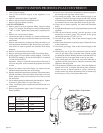
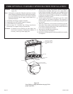
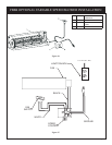
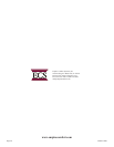
A factory installed junction box is located on the lower
right side of the fireplace. Wiring must be fed to the
junction box and attached to the receptacle that is provided.
Leave approximately 6" of wire in the junction box for
connection.
Attach black wire to one side of the receptacle and white
wire to opposite side of receptacle. The ground wire should
be attached to the green (ground) screw.
Install the receptacle into the junction box. Attach cover
plate.
Figure 28
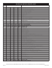
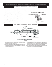
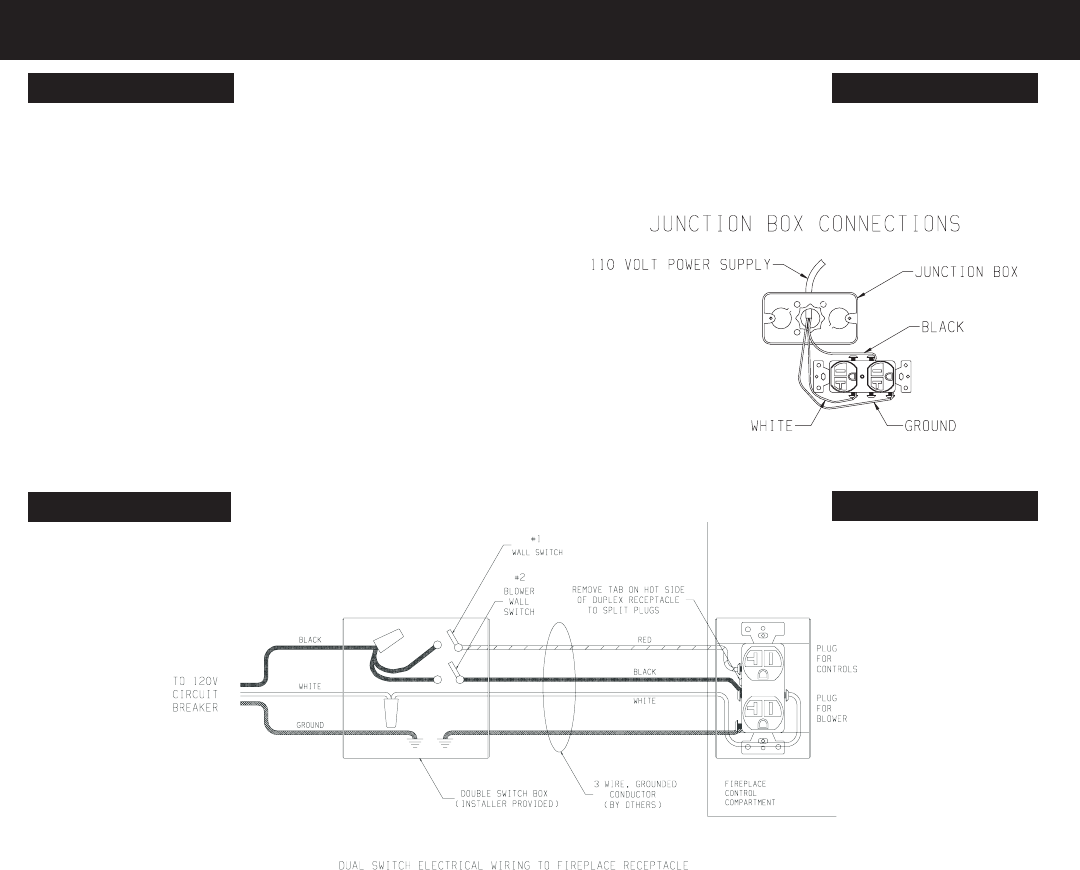
STANDARD MILLIVOLT VALVE MODELS
120V DIRECT IGNITION VALVE MODELS
1. To wire Junction Box Receptacle, remove the tab on the side of
the receptacle (hot side) to split receptacle. This will be required
to separate blower and valve circuits.
2. Power for switched and live sides of Duplex Receptacle must come
from the same power source. (One circuit breaker on main panel
must switch all power off.)
3. From the wall box to the fireplace a 3-wire conductor with ground is
recommended, however (2) two-wire conductors with grounds may
be used in place of a 3-wire conductor with a ground if the black
wires from the thermostat and blower switch are identified.
4. Two wall switches, or a wall switch and thermostat may be used
to activate the two receptacle plugs independently.
Figure 29
JUNCTION BOX WIRING INSTALLATION INSTRUCTIONS