


Page 26 19400-3-0406
1. Turn off the gas supply.
2. Turn off the electrical supply to the appliance if so
equipped.
3. Open or remove glass doors if applicable.
4. Remove top louver and lower bottom louver.
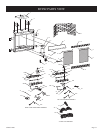
5. Remove logs from burner assembly.
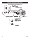
VALVE CONVERSION
6. Remove plastic cap from regulator fitting. Unscrew fitting
using a 7/16" wrench. Turn fitting over so end of fitting marked
"LPG" is visible. Tighten fitting (snug only). Replace plastic
cap.
7. Remove 1/4" screw from air shutter.
8. Located to the right of electrodes is a burner hold-down tab.
Using needle-nose pliers, bend burner hold-down tab off the
main burner.
9. Remove main burner by pivoting main burner forward as you
slide main burner from left to right. Be careful as you remove
main burner in order to protect the electrodes from being
damaged.
10. Remove air shutter from orifice fitting.
11. Remove natural gas main burner orifice from orifice fitting.
12. Install propane/LP main burner orifice marked 1.35mm for
BVD34FP50, marked 1.45 mm for BVD36FP52, or marked
1.65mm for BVP42FP52.
Important: Failure to install the correct orifice will result in
unit over-firing that could overheat the appliance and result
in a fire.
13. Replace air shutter onto orifice fitting. Air shutter must be
threaded and bottomed-out onto orifice fitting.
14. Replace main burner onto burner assembly. Place main burner
beneath electrodes, slide main burner from right to left into
burner location, and pivot main burner away from you and
into air shutter.
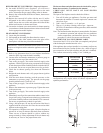
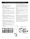
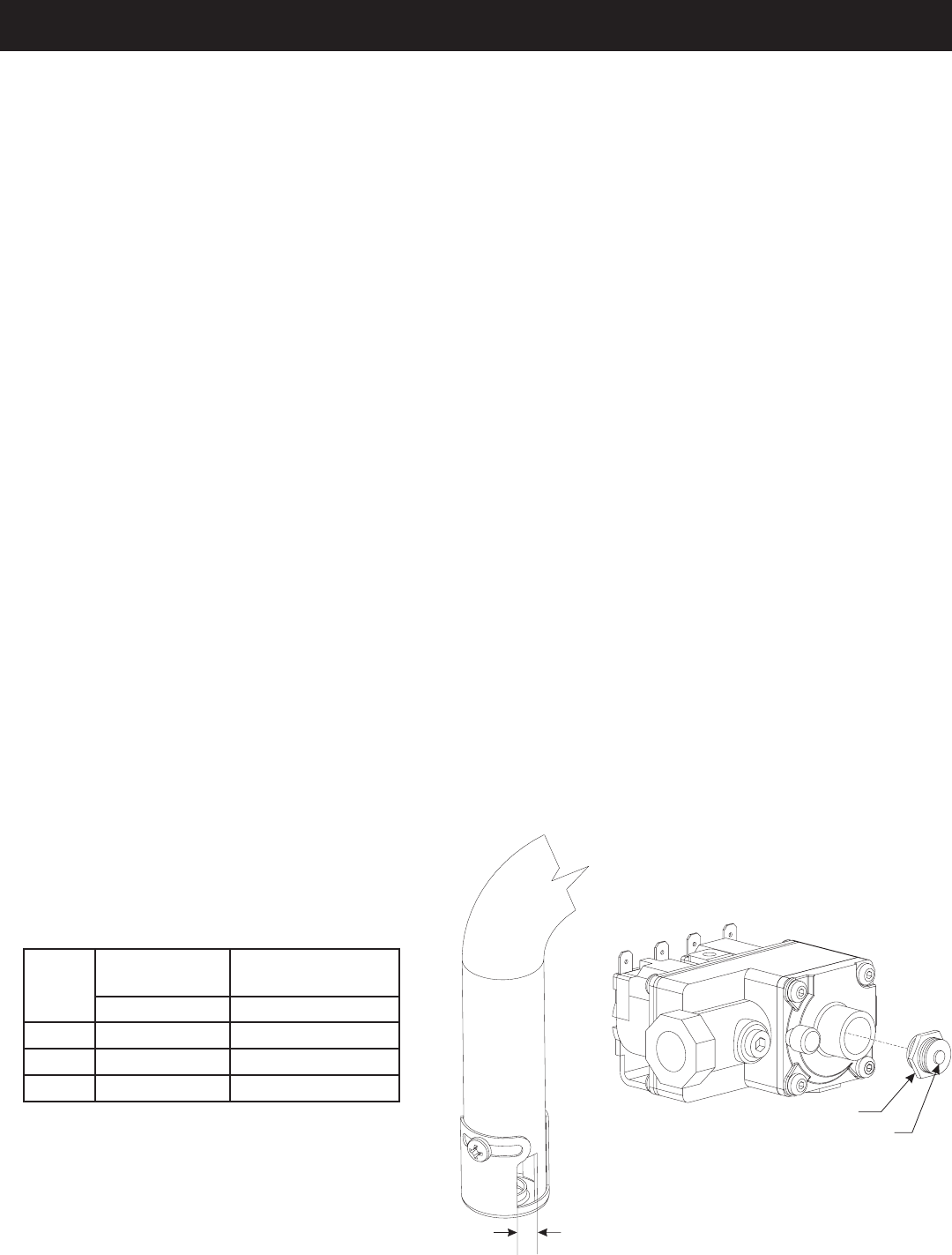
15. Set air shutter opening as indicated by the chart below. Tighten
air shutter in place with 1/4" screw from step 7.
16. Using needle-nose pliers, bend burner hold-down tab over
main burner.
17. Refer to log placement, pages 14 and 15 to place logs onto
burner assembly.
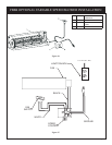
18. Loosen screw and attach a manometer or pressure gauge to
the outlet pressure tap of the control valve.
19. Turn on the gas supply. Turn on the electrical supply to the
appliance. Check for gas leaks using soap and water solution
or leak detection solution. Bubbles indicate a leak that MUST
be corrected. Do not use an open flame to test for gas leaks.
20. Check the air shutter opening. See chart and illustration
below.
21. Relight the main burners and verify proper burner ignition and
operation.
22. With the main burner burning, read the pressure on the
manometer or pressure gauge. The pressure on the gauge
should read between 9.8" and 10.2" w.c.
23. Turn off the gas supply. Turn off the electrical supply to the
appliance.
24. Remove the manometer or pressure gauge. Tighten the screw
in the pressure tap.
25. Turn on the gas supply. Turn on the electrical supply to the
appliance.
26. Immediately test all gas line connections and the control
valve for gas leaks using a soap and water solution or other
gas detection solution. Bubbles indicate a leak that MUST be
corrected. Do not use an open flame to test for gas leaks.
27. Using a ball point pen, fill out the conversion label that is
supplied with the conversion kit. Place the conversion label
adjacent to the rating plate.
28. Test operation of fireplace once again. Allow the fireplace to
operate for at least 10 minutes and check flame coloration.
Flames on rear of burner should be yellow without any
orange-colored tip. Minor adjustment of the air shutter may
be necessary to "tune in" the proper flame color.
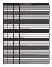
Model AIR SHUTTER
SETTINGS
BURNER ORIFICE
Opening "A" Propane/LP Orifice
BVD34 5/16" (8mm) 1.35mm
BVD36 5/16" (8mm) 1.45mm
BVP42 Full Open 1.65mm
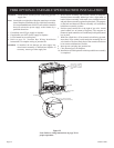
“A”
REGULATORFITTING
NOTE: STAMPEDWITH
GASTYPE SET FORUSE
Maxitrol Valve Conversion
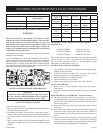
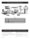
DIRECT IGNITION PROPANE/LP GAS CONVERSION