


Page 22 19400-3-0406
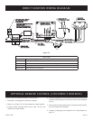
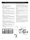
BURNER ORIFICE CONVERSION - Slope style burners
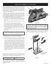
8b. On model BVP42FP3 series fireplaces, you will have a
rectangular slope style burner. To gain access to the main
orifice, disconnect the gas supply tubing at the air shutter.
9b. Remove the orifice holder from the air shutter, then remove
the NG orifice.
10b. Replace the removed NG orifice with the new LP orifice
designated in the orifice reference chart for your fireplace
model. Secure the new orifice and replace the orifice/orifice
holder back into the air shutter and secure.
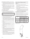
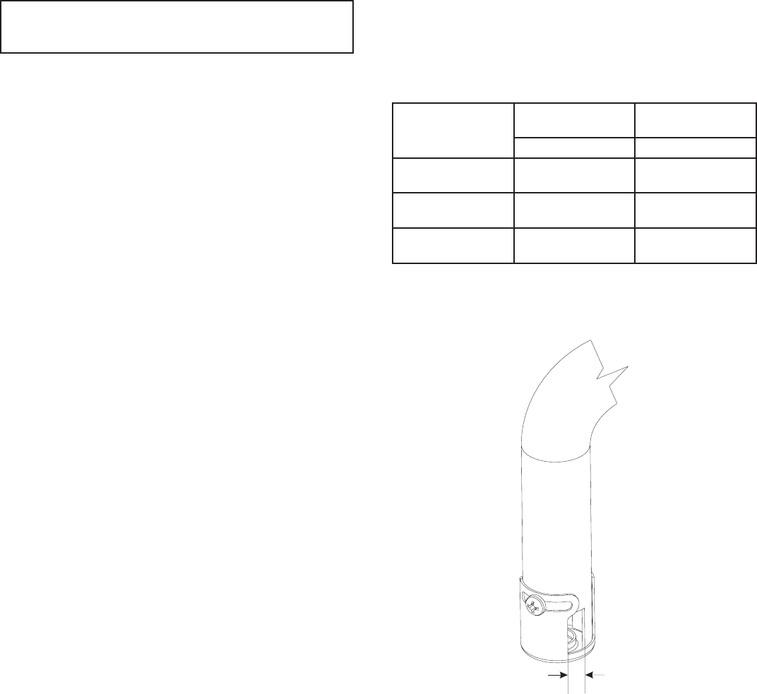
11b. Loosen the air shutter screw and reset the air shutter opening
in accordance with the dimension shown in the reference chart
for the appropriate model fireplace.
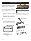
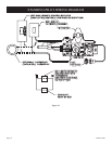
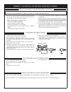
PILOT ORIFICE CONVERSION
12. Locate the pilot assembly.
13. Pull upward on the round pilot flame hood to remove.
14. Using a 5/32" Hex Allen wrench, remove the pilot orifice,
then replace with the new pilot orifice marked #35.
IMPORTANT: Failure to install the correct orifice will result
in unit over-firing that could overheat the appliance and result
in a fire.
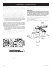
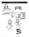
15. Refer to log placement found in your fireplace installation
manual to place logs onto the burner assembly.
16. Loosen screw and attach a manometer or pressure gauge to
the outlet pressure tap of the control valve.
17. Turn on the gas supply. Turn on the electrical supply to the
appliance. Check for gas leaks using a soap and water solution
or leak detection solution. Bubbles indicate a leak that MUST
be corrected. Do not use an open flame to test for gas leaks.
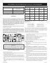
18. Check the air shutter opening. See chart and illustration
below.
19. Relight the main burners and verify proper burner ignition
and operation.
20. With the main burner burning, read the pressure on the
manometer or pressure gauge. The pressure on the gauge
should read between 9.8" and 10.2"w.c.
21. Turn off the gas supply. Turn off the electrical supply to the
appliance.
22. Remove the manometer or pressure gage. Tighten the screw
in the pressure tap.
23. Turn on the gas supply. Turn on the electrical supply to the
appliance.
24. Immediately test all gas line connections and the control valve
for gas leaks using a soap and water solution or gas detection
for solution. Bubbles indicate a leak that MUST be corrected.
Do not use an open flame to check for gas leaks.
25. Using a ball point pen, fill out the conversion label that is
supplied with the conversion kit. Place the conversion label
adjacent to the rating plate.
26. Test operation of fireplace once again. Allow the fireplace to
operate for at least 10 minutes and check flame coloration.
Flame on rear of burner should be yellow without any
orange-colored tip. Minor adjustment of the air shutter may
be necessary to "tune in" the proper flame color.
The burner flame and pilot flame must be checked for proper
flame characteristics, as outlined in this manual.
VERIFYING INPUT RATE OF CONVERTED
FIREPLACE
The input of the fireplace must be checked as follows:
1. Turn off all other gas appliances. Clock the gas meter and
determine the number of seconds required to consume one
cubic foot of gas.
2. 3600 ÷ time (in seconds) = cu. ft. per hour.
3. Then cu. ft. per hour x heating value of gas = input rate
(BTU/Hr). On installation without gas meters, check manifold
for proper pressure.
Note: The rate noted on the data plate is measured after 45 minutes
of continuous operation and adjusted for test conditions
such as temperature, and barometric pressure. The above
procedure is a check for correct conversion only.
PLACEMENT OF GAS CONVERSION LABEL
Conversion label 2139 is to be filled out completely and placed
with the data plate attached near the valve.
If the appliance has not been installed, or a warranty card has not
been returned to Empire Comfort Systems, Inc., check off type of
gas converted to on card (for reference once the unit is installed).
Also, indicate conversion by adding "Conv." behind gas.
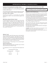
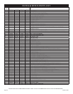
MODEL AIR SHUTTER
SETTINGS
BURNER
ORIFICE
Opening "A" Propane/LP
BVD34 5/16"
(7.9mm)
1.35mm
P-289
BVD36 5/16"
(7.9mm)
1.45mm
P-208
BVP42 FULL OPEN 1.65mm
P-250
Air shutter settings shown are factory settings. Some venting
configurations may require minor air shutter adjustments for
optimum performance.
“A”