


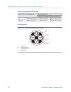
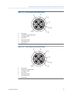
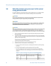
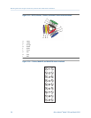

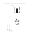

Sensor and remote core processor terminal designationsTable 3-7:
Wire color Sensor terminal Remote core processor terminal Function
Black No connection Ground screw (see notes) Drain wires
Brown 1 1 Drive +
Red 2 2 Drive –
Orange 3 3 Temperature –
Yellow 4 4 Temperature return
Green 5 5 Left pickoff +
Blue 6 6 Right pickoff +
Violet 7 7 Temperature +
Gray 8 8 Right pickoff –
White 9 9 Left pickoff –
Notes
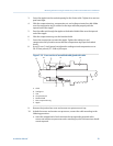
• Ground the shield drain wires (the black wire) only on the remote core processor end,
by connecting it to the ground screw inside the lower conduit ring. Never ground to
the core processor’s mounting screw. Never ground the cable at the sensor junction
box.
• Ground the cable braid on both ends, by terminating it inside the cable glands.
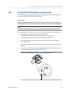
b. Tighten the screws to hold the wires in place.
c. Ensure integrity of gaskets, grease all O-rings, then replace the junction box
cover and remote core processor end-cap and tighten all screws, as required.
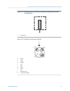
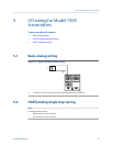
3.7.1
Sensor and remote core processor terminals
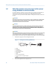
Mounting and sensor wiring for remote core processor with remote sensor installations
30 Micro Motion
®
Model 1500 and Model 2500