


• Twisted pair construction.
• Applicable hazardous area requirements, if the core processor is installed in a
hazardous area.
• Wire gauge appropriate for the cable length between the core processor and the
transmitter.
Wire gaugeTable 2-1:
Wire gauge Maximum cable length
VDC 22 AWG (0.35 mm
2
) 300 ft (90 m)
VDC 20 AWG (0.5 mm
2
) 500 ft (150 m)
VDC 18 AWG (0.8 mm
2
) 1000 ft (300 m)
RS-485 22 AWG (0.35 mm
2
) or larger 1000 ft (300 m)
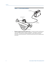
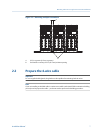
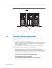
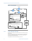
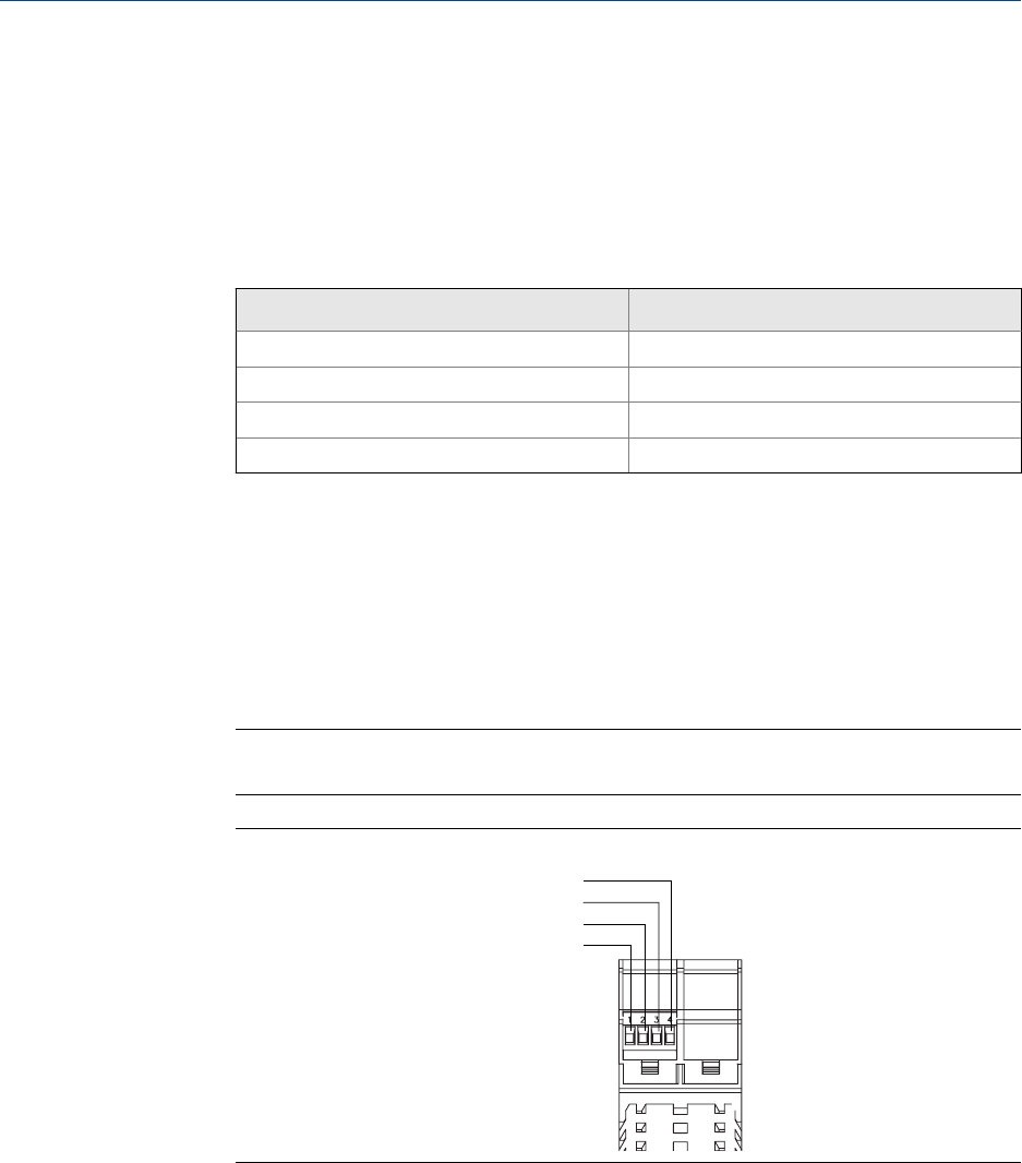
2.3 Wire the transmitter to the sensor
1. Connect the cable to the core processor as described in the sensor documentation.
2. Connect the four wires from the core processor to terminals 1–4 on the transmitter.
Important
Do not ground the shield, braid, or drain wires at the transmitter.
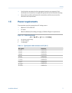
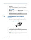
Terminal connections for 4-wire cableFigure 2-5:
RS-485B
RS-485A
VDC–
VDC+
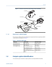
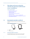
2.4 Ground the flowmeter components
In 4-wire remote installations, the transmitter and sensor are grounded separately.
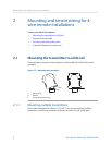
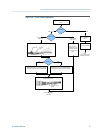
Mounting and sensor wiring for 4-wire remote installations
10 Micro Motion
®
Model 1500 and Model 2500