


- 30 -
Unit V MAINTENANCE
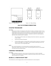
ROUTINE MAINTENANCE
The detector requires no periodic calibration. To maintain maximum sensitivity, the viewing
windows should be cleaned on a routine basis depending on the type and amount of contaminants
in the area.
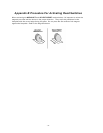
The rubber O-rings on the detector housing are used to ensure it is watertight. The housings
should be opened periodically and the O-rings inspected for breaks, cracks or dryness. To test
them, remove the O-rings from the detector housing and stretch them slightly. If cracks are visible,
the O-ring should be replaced. If they feel dry to the touch, a thin coating of lubricant should be
applied. When re-installing the O-rings, be sure that they are properly seated in the groove on the
housing.
These O-rings must be properly installed and in good condition to prevent water from entering the
detector and causing failure. The life expectancy of rubber O-rings varies, depending on the type
and amount of contaminants present in the area. The person who maintains the system must rely
on experience and common sense to determine how frequently the rings should be inspected. A
coating of lubricant should also be applied to the enclosure threads before reassembling the
detector to help prevent moisture from entering.
CAUTION
The O-ring should be lubricated with polyalphaolefin grease, such as GRS-450 made by
CPI Engineering. Silicone based lubricants should never be used if catalytic type
combustible gas sensors are being used in conjunction with the UV detectors, since
silicone lubricant on or near the combustible gas sensor will cause permanent damage to
the sensing element.
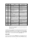
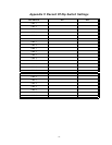
TROUBLESHOOTING
The Automatic vi (visual integrity) feature continuously checks the detectors for correct response.
If a problem is detected, the fault LED will turn on, the left side of the digital display will indicate
which channel has the problem and the right side of the digital display will show “OIL” or “OIH”
The fault relay will become de-energized.
If a fault is in the detector or wiring, the left side of the display will indicate which detector is
affected. The right side of the display will indicate by code number the type of fault. If the fault is in
the microprocessor circuitry, the fault LED will turn on, but the left side of the digital display will
remain blank. Refer to Table 3 for a detailed explanation of the status/fault codes.
DEVICE REPAIR AND RETURN
The detector and controller are not designed to be repaired by the customer in the field. If a
problem should develop, first carefully check for proper wiring and programming. If it is
determined that the problem is caused by an electrical malfunction, the unit must be returned to
the factory for repair.
Net Safety Monitoring Inc encourages its distributors to make advance replacement units
available to the user during the warranty period. This allows Net Safety Monitoring Inc. to take
time to repair the unit completely while users keep their operations running with the advance
replacement unit.