- 23 -
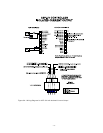
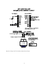
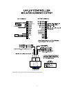
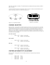
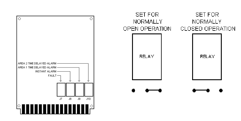
Figure 11c - Relay Position
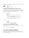
Figure 11d - Relay Settings
Unit IV SYSTEM OPERATION
STARTUP PROCEDURE
CAUTION
Placing the controller in the Bypass mode inhibits its outputs, preventing actuation of any
extinguishing or alarm circuits that are connected. For maximum safety, however, secure
output loads (remove power from any devices that would normally be actuated by the
system) before manually testing the system. Remember to place this same equipment
back into service when the test is complete.
1. After setting the DIP switches and making all electrical connections, apply power
to the controller.
2. Perform the Checkout Procedure.
3. If the controller appears to be operating normally (performs power-up countdown
and then shows ‘Nor’ on the display), remove mechanical blocking devices and
restore power to the extinguishing loads.
NOTE
Be sure that the detector is correctly aimed at the potential hazard and that no
obstructions interfere with its line of vision. UV absorbing gases should not exist between
the detector and the potential hazard.
CHECKOUT PROCEDURE
CAUTION
When testing the system, be sure to secure all output devices to prevent unwanted
activation of this equipment and remember to place these same devices back into service
when the check-out is complete.
MANUAL vi CHECK/COUNT TEST
The Automatic vi (visual integrity) feature checks the detectors for correct response.


