


- 4 -
BASIC OPERATION - CONTROLLER
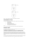
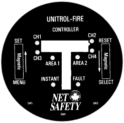
CONTROLLER FACEPLATE DESCRIPTION
The controller faceplate provides LEDs and two digital displays for identifying status conditions, a
bar graph display for indicating an alarm condition and MENU/SET and SELECT/RESET push-
button switches (See appendix for instructions on activation) for testing and resetting the system.
Refer to Figure 3.
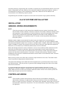
Figure 3 - Controller Face-Plate
< Digital Displays - The left side of the digital display is normally off. If a fire alarm
or visual integrity fault is detected, it indicates the channel number of the alarm or
fault. The digital displays indicate system status including system error codes,
visual integrity (vi) faults, system faults or fire alarms. The right side of the
display shows ‘nor’ in normal operating mode. If more than one channel is in an
alarm or fault condition the digital displays will cycle through these channels.
Since at least one side of the display is always lit they also function as a power
indicator.
< Bar Graph Display - Normally off. Flashing when fire detected in any area.
< Instant LED - (no time delay) Flashes when any detector signal exceeds the fire
sensitivity setting.
< Area 1 & 2 LEDs - (Area 1 only for U1F) If the selected “voting” criteria of the
area and the preset time delay has elapsed the corresponding LED starts
flashing.
< Fault LED - flashes upon detection of an overall system fault or vi fault.
< Channel LEDs - (1, 2 or 4 depending on model) flash to indicate detector in
alarm and remain illuminated until reset after an alarm condition has returned to
normal.
< MENU/SET Reed Switch - is used to enter the main menu, to toggle through
menu selections and in conjunction with the SELECT/RESET Reed Switch to
enter the special functions menu.
< SELECT/RESET Reed Switch - is used for a basic system reset, menu selection
and with the MENU/SET Reed Switch to enter the special functions menu. This
switch is also used during the manual vi test.