


- 20 -
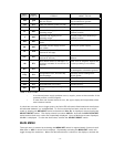
The switch values are added together. These switches are factory set to a sensitivity of 24 counts
per second, as shown in the example.
Example: SW 4.1 ON
SW 4.2 ON sensitivity
SW 4.3 OFF = 24 cps
SW 4.4 OFF
FIRE AREA VOTING SEQUENCE (not applicable to U1F)
SW 4.5, SW 4.6 and SW 4.8 select voting sequence which can be Fire Area 1 only (all detectors
in one area) or Fire Area 1 separate from Fire Area 2. When separate, Fire Area 1 consists of
detector 1 (1 and 2 for U4F) and Fire Area 2 consists of detector 2 (detector 3 and 4 for U4F).
Switch SW 4.7 should be placed in the ‘OFF’ position at all times.
Fire Area 1 Separate from Fire Area 2:
< SW 4.7 OFF
< SW 4.8 ON
< SW 4.5 programs Fire Area 1 (detector 1 for U2F) (detectors 1 and 2
for U4F)
OFF: votes one of two detectors (always OFF for U2F)
ON: votes two of two detectors
< SW 4.6 programs Fire Area 2 (detector 3 for U2F) (detectors 3 and 4
for U4F)
OFF: votes one of two detectors (always OFF for U2F)
ON: votes two of two detectors
Fire Area 1 only:
< SW 4.8 OFF
< SW 4.7 OFF
< SW 4.6 OFF
< SW 4.5 OFF: votes any one of all detectors
ON: votes any two of all detectors
RELAY OUTPUTS LATCHING/NON-LATCHING
The alarm relays are programmed together for latching or non-latching operation (the fault relay is
only non-latching).
< 5.1: ON: non-latching operation
OFF: latching operation
NOTE
Latched outputs are unlatched by activating the RESET switch.
RELAY OUTPUTS ENERGIZED/DE-ENERGIZED
The area and instant alarm relays can be programmed for normally energized or normally de-
energized operation using SW 5.2 . The fault relay is always normally energized. SW 5.2 is factory
set to de-energized operation (ON)