


- 19 -
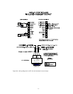
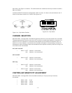
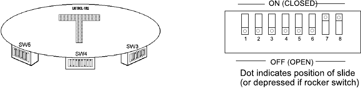
Figure 11b - Dip Switch
time delay. See Figure 11a below. The switch banks are numbered from top to bottom as SW 5,
SW 4 and SW 3.
Individual ON/OFF switches are designated “SW X.Y where ‘X’ refers to the switch bank and ‘Y’
refers to the switch number on ‘X’ bank. See Figure 11b.
.
Figure 11a - Dip Switch Position
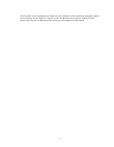
CHANNEL SELECTION
Switches SW 3.1 through SW 3.4 enable the detectors that are to be connected to the controller.
The appropriate switch must be set to the ‘OFF’ position to enable each detector connected. If a
switch is off but no detector is connected in that location the controller will indicate a fault. If a
switch is on, but a detector is connected, the controller will appear to be operating correctly but
that detector will be eliminated from the Automatic vi test sequence and any faults occurring in its
circuit will not be annunciated.
U1F, U2F and U4F
< SW 3.1: OFF: detector 1 connected
ON: detector 1 not connected
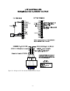
U2F and U4F
< SW 3.2: OFF: detector 2 connected
ON: detector 2 not connected
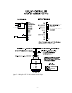
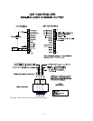
U4F only
< SW 3.3: OFF: detector 3 connected
ON: detector 3 not connected
< SW 3.4: OFF: detector 4 connected
ON: detector 4 not connected
CONTROLLER SENSITIVITY ADJUSTMENT
Switches SW 4.1 through SW 4.4 set controller sensitivity in 8 cps (counts per second)
increments.
< SW 4.1 ON: 8 cps
< SW 4.2 ON: 16 cps
< SW 4.3 ON: 32 cps
< SW 4.4 ON: 64 cps