- 29 -
area output is reached (‘gPA’ = Area 1 and ‘gPb’ = Area 2), then activate the SELECT/RESET
switch.
When an area has been chosen for forced current output, the left side of the display will alternate
between ‘GPn’ and ‘FoP’ and the right side of the display will show what type of current output is
being placed on the current output line:
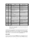
FLt -> Fault (1mA)
POE -> Power Error (2mA)
Nor -> Normal (4mA)
OP1 -> Visual Integrity Error Channel 1 (5mA)
OP2 -> Visual Integrity Error Channel 2 (6mA)
OP3 -> Visual Integrity Error Channel 3 (7mA)
OP4 -> Visual Integrity Error Channel 4 (8mA)
OPA -> Visual Integrity Error on more than one channel (9mA)
in1 -> Instant Alarm Channel 1 (15mA)
in2 -> Instant Alarm Channel 2 (16mA)
in3 -> Instant Alarm Channel 3 (17mA)
in4 -> Instant Alarm Channel 4 (18mA)
inA -> Instant Alarm on more than one channel (19mA)
Fir -> Area Alarm (19.5mA)
The controller will start with the Fault output and the Reed Switches are used to scroll up and
down through the different outputs. To exit this mode, scroll down past the Fault output selection
until ‘rtn’ is displayed then wait 10 seconds. The controller will return to the normal operating
mode.
CURRENT CALIBRATION MODE (CuC)
The next selection in the special function menu is the current calibration mode. This mode is
selected to calibrate the current outputs. Upon successful entry into this mode the left side of the
display will flash ‘gPn’. Activate the MENU/SET switch until the desired area output is reached
(‘gPA’ = Area 1 and ‘gPb’ = Area 2), then activate the SELECT/RESET switch. Once an area
has been selected, the left side of the display will alternate between ‘CuC’ and the area that is
being calibrated. The lower display will show a constant which will rise and fall as the current is
adjusted (constant does not show the current on the outputs), and the instant LED will flash. Place
a milliamp meter between the Area current output and common ground. Use the Reed Switches to
raise and lower the current. Once the current measured is as close to 4mA as possible, do not
activate any switches for 10 seconds. After 10 seconds have gone by the number shown on the
right side of the display will change to a much higher number. The instant LED will be
extinguished and the area LED will begin flashing. This tells the operator to calibrate the current
output for the high end of the current output range. Use the Reed Switch to raise or lower the
current output until it is as close as possible to 20 mA. Do not activate any switches for 10
seconds and the controller will return to the normal operating mode.
ADDRESS SET MODE (Adr Set) (Do not use)
Do not use the final selection in the special function menu which is to set the controllers address
for the CAN system. When the left side of the display shows ‘Adr’ and the right side of the display
shows ‘SEt’ activate the SELECT/RESET switch. The left side of the display will alternate
between ‘Adr’ and ‘SEt’ and the right side of the display will show the current address. Use the
Reed Switch to raise and lower the address. Once the address is correct, do not activate any
switches for 10 seconds and the controller will return to the normal operating mode.


