


6
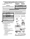
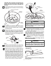
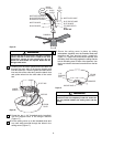
12. Position one of the blade assemblies onto the
motor hub and secure blade assembly using two
1/4-20 x 1/2” oval head flange screws (provided).
Repeat for all blade assemblies (Figure 8).
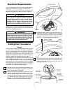
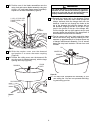
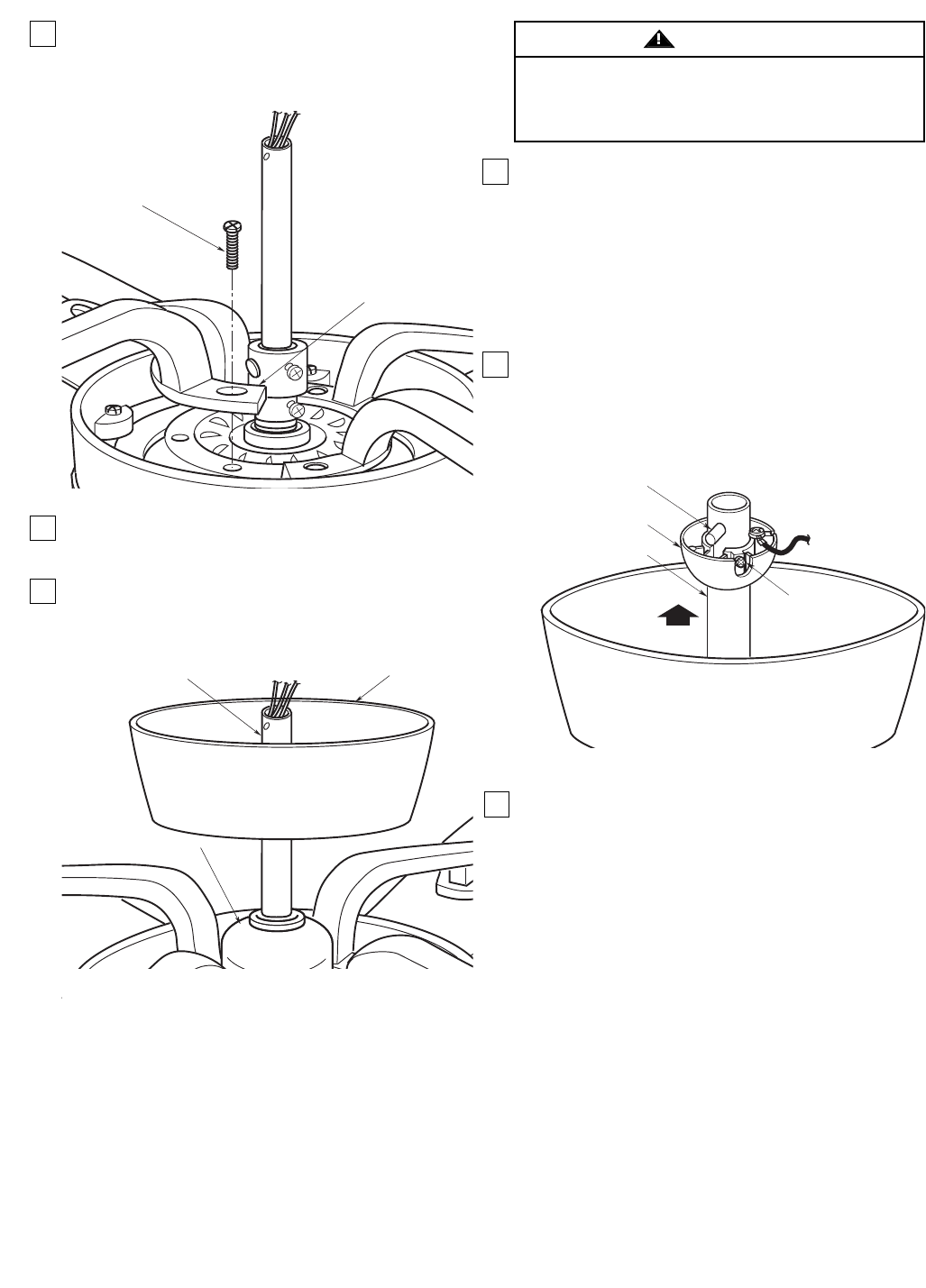
13. Slide the coupler cover over the downrod
and position it to cover the motor coupling
(Figure 9).
14. Position the ceiling cover over the downrod. Be
sure the cover is oriented correctly, with the large
opening at the top (Figure 9).
BLADE
ASSEMBLY
1/4-20 x 1/2" OVAL HEAD
FLANGE SCREW (2 PER
FLANGE)
Figure 8
CEILING
COVER
COUPLING COVER
DOWNROD
Figure 9
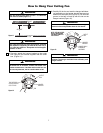
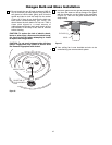
It is critical that the pin in the hanger ball is properly
installed and the setscrews securely tightened.
Failure to verify that the pin and setscrews are
properly installed could result in the fan falling.
WARNING
15.Reinstall the hanger ball on the downrod (Figure
10) as follows. Route the motor leads through the
hanger ball and slide the hanger ball over the
downrod. Install the pin through the holes at the
top of the downrod and slide the hanger ball up
the downrod, aligning the ball so the pin in cap-
tured in the groove in the top of the hanger ball.
Pull the hanger ball up tight against the pin and
securely tighten the setscrew in the hanger ball. A
loose setscrew could create fan wobble.
16.The fan comes with blue, black and white leads
that are 80-inches long. Before installing the fan,
measure up approximately 6 to 9-inches above top
of hanger ball/downrod assembly. Cut off excess
leads and strip back insulation 1/2-inch from end
of leads.
17. You have now completed the assembly of your
new ceiling fan. You can now proceed with hang-
ing and wiring your fan.
PIN
HANGER BALL
SETSCREW
DOWNROD
Figure 10