


4
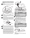
Electrical Requirements
Your new ceiling fan will require a grounded electrical
supply line of 120 volts AC, 60 Hz, 15 amp circuit.
The outlet box must be securely anchored and
capable of withstanding a load of at least 50 pounds.
To reduce the risk of fire, electric shock, or personal
injury, mount fan to outlet box marked “Acceptable
for Fan Support of 50 lbs. or less”, and use screws
supplied with outlet box. Most outlet boxes
commonly used for support of light fixtures are not
acceptable for fan support and may need to be
replaced. Consult a qualified electrician if in doubt.
WARNING
Ceiling Fan Procedures
General
Your Emerson Ceiling Fan/Light Wall Control consists
of a wall mount transmitter. The SW114 transmitter
works in conjunction with the SW105 Receiver
(purchased separately). The receiver is mounted
under the fan ceiling cover. The wall control is
designed to separately control your ceiling fan speed,
direction, uplight and downlight intensity, page 11.
Code switches in the wall control and receiver may be
set in 16 different positions. If your fan and light go on
and off without using your control, you may be getting
interference from other transmitters such as garage
door openers, car alarms or security systems.
To remedy this situation, simply change the combina-
tion code in your wall control and receiver.
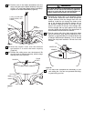
If your fan is to replace an existing ceiling light fixture,
turn electricity off at the main fuse box at this time and
remove the existing light fixture.
Turning off wall switch is not sufficient. To avoid
possible electrical shock, be sure electricity is turned
off at the main fuse box before wiring. All wiring must
be in accordance with National and Local codes and
the ceiling fan must be properly grounded as a
precaution against possible electrical shock.
WARNING
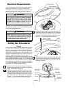
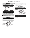
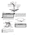
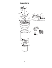
1. Remove the fan motor and housing assembly from
the styrofoam packaging and position it so that the
bottom of the motor is facing you.
2. Position the bottom styrofoam section on a flat
surface exposing the large center hole for fan
motor placement. Place the fan motor housing into
the hole so that the bottom of the motor is facing
up. Position the lower housing over the fan motor
(Figure 1). The styrofoam section will hold the
assembly while you perform the following steps.
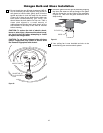
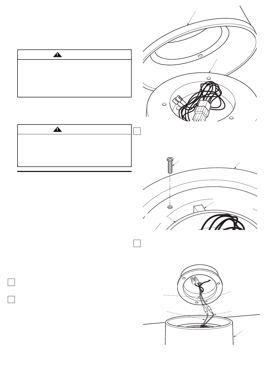
3. Install the lower housing onto the fan motor by
orientating the three protruding keys into the slots
on the lower housing to secure. Fasten the lower
housing onto the fan motor using the three
#10-24 x 1” lower housing screws (Figure 2).
#10-24 x 1" LOWER
HOUSING SCREW (3)
LOWER
HOUSING
PROTRUDING KEY (3)
FAN MOTOR
Figure 2
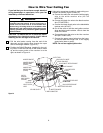
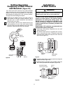
LIGHT KIT
WHITE WIRE
FAN MOTOR
WHITE WIRE
FAN MOTOR
BLUE WIRE
LIGHT KIT
BLUE WIRE
LIGHT KIT
ASSEMBLY
Figure 3
4. Connect the fan motor blue wire to the blue wire
from the light kit assembly; connect the fan motor
white wire to the white wire from the light kit
assembly (Figure 3).
LOWER HOUSING
FAN HOUSING
Figure 1