


5
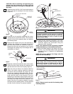
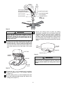
CAUTION: Before installing and tightening the
screws, be sure there are no wires pinched
between the bottom of the light kit assembly and
fan motor.
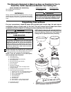
5. Install the three #10-24 x 5/16” pan head screws to
secure the light kit assembly to the lower housing
(Figure 4).
#10-24 x 5/16" PAN HEAD
SCREW (3)
LIGHT KIT
ASSEMBLY
LOWER
HOUSING
Figure 4
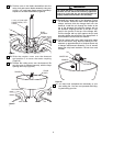
6. Carefully turn the partially assembled fan motor
housing onto the styrofoam section. The styrofoam
section will hold the assembly while you perform
the following steps.
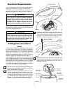
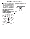
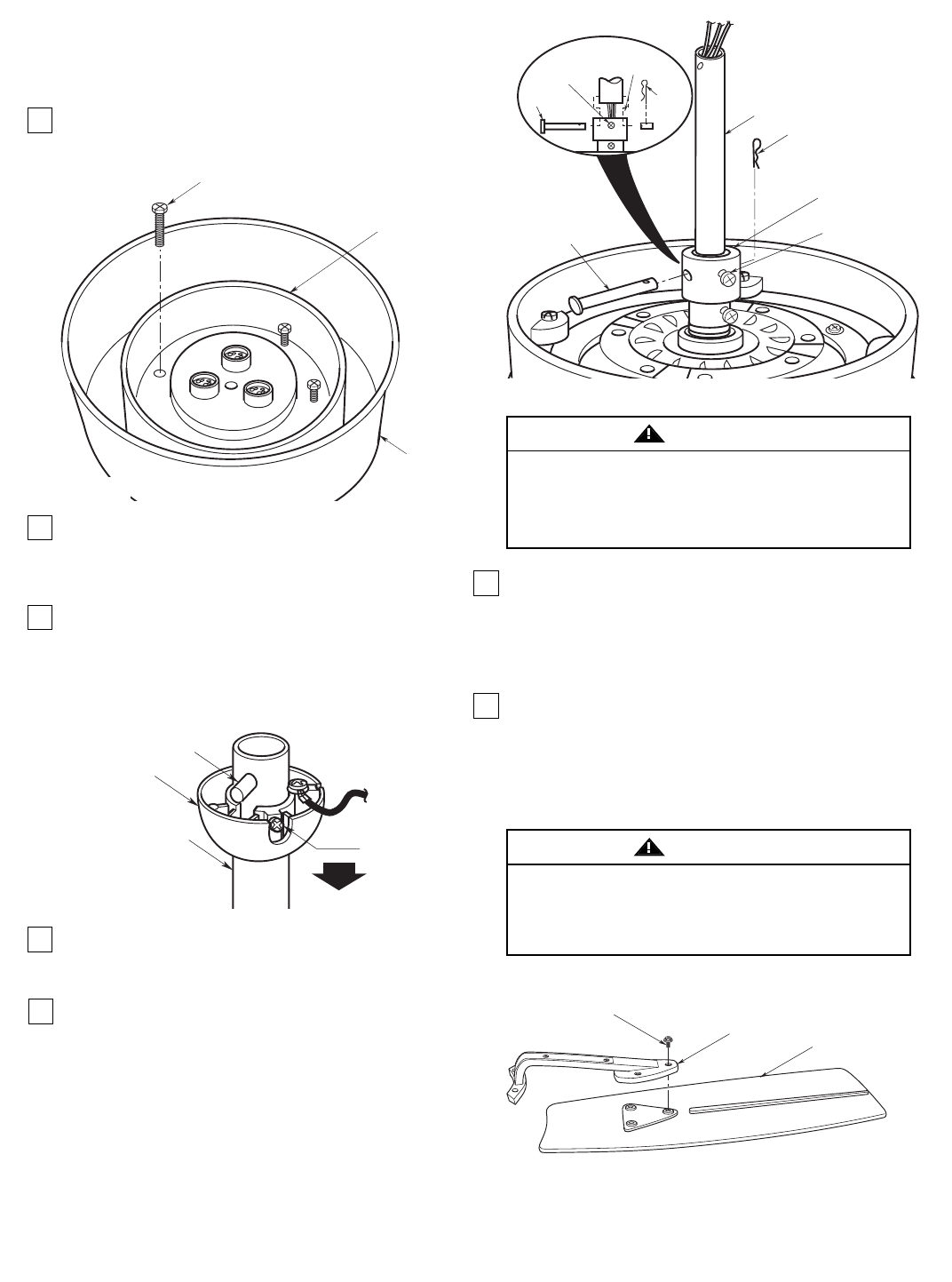
7. Remove the hanger ball from the downrod by
loosening the setscrew in the hanger ball until the
ball falls freely down the downrod (Figure 5).
Remove the pin from the downrod, then remove
the hanger ball. Retain the pin and hanger ball for
reinstallation in Step 15.
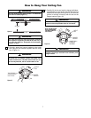
8. Separate, untwist and unkink the three motor leads.
Route the motor leads through the downrod and
seat the downrod in the motor coupling (Figure 6).
PIN
HANGER
BALL
SETSCREW
DOWNROD
Figure 5
Figure 6
SETSCREW (2)
CLEVIS PIN
HAIRPIN CLIP
DOWNROD
HAIRPIN
CLIP
MOTOR
COUPLING
SETSCREW (2)
CLEVIS PIN
MOTOR
COUPLING
10. Install the two setscrew (supplied) in the motor
coupling (Figure 6). While pulling up on the
downrod, tighten the setscrews using the
setscrew wrench (supplied).
NOTE: The setscrews must be properly installed
as described above, or fan wobble could result.
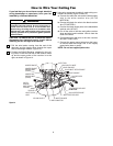
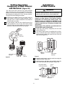
11. Mount the blade flanges to fan blades using three
#10-24 x 1/4” oval head blade screws per blade
(supplied) (Figure 7). Repeat for all blade/flange
assemblies.
NOTE: Be sure to position the flange onto the
blade with the ribs side up.
It is critical that the clevis pin in the motor coupling
is properly installed and the setscrew is securely
tightened. Failure to verify that the pin and setscrew
are properly installed (as shown in Figure 2) could
result in the fan falling.
WARNING
To reduce the risk of personal injury, do not bend the
blade flange when installing the blade flanges,
balancing the blades or cleaning the fan. Do not
insert foreign objects in between rotating fan blades.
WARNING
9. Align the clevis pin holes in the downrod with the
holes in the motor coupling. Install the clevis pin
and secure with the hairpin clip (Figure 6). (Pin
and clip are supplied in loose parts bag.) The cle-
vis pin must go through the holes in the motor cou-
pling and the holes in the downrod. Push the
straight leg of the hairpin clip through the hole near
the end of the clevis pin until the curved portion of
the hairpin clip snaps around the clevis pin. The
hairpin clip must be properly installed to prevent
the clevis pin from working loose. Pull the downrod
to make sure the clevis pin is properly installed.
#10-24 x 1/4" OVAL
HEAD BLADE SCREW
(3 PER BLADE)
FLANGE
BLADE
Figure 7
NOTE: Take care not to scratch fan housing when
installing blades.