


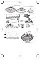
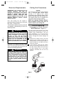
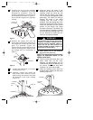
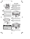
#10-32 x 5/16" OVAL
HEAD FLANGE SCREW
(2 per flange)
BLADE
ASSEMBLY
MOTOR HOUSING
ASSEMBLY FLANGE
SLOT
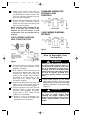
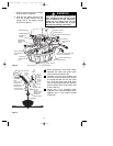
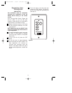
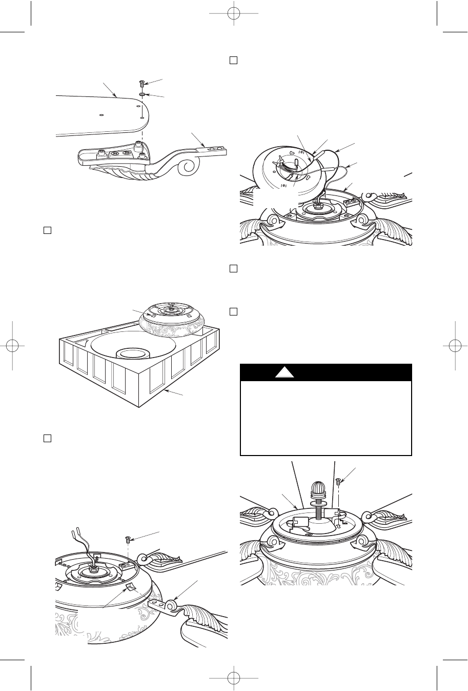
4. Securely connect the black wire
connector of the light fitter assembly to
the black motor wire connector.
Securely connect the white wire of the
light fitter assembly to the white motor
wire (Figure 9).
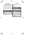
5. Position the light fitter assembly so that
the three holes align with the one hole
and two keyhole slots in the light kit
adapter plate (Figure 10).
6. Attach the light fitter assembly to the
light kit adapter plate by securely
installing the three #8-32 x 1/4” pan
head screws (supplied in the loose
parts bag) (Figure 10).
MOTOR HOUSING
BLACK WIRE
MOTOR HOUSING
WHITE WIRE
LIGHT FITTER
BLACK WIRE
LIGHT FITTER
WHITE WIRE
LIGHT FITTER
ASSEMBLY
LIGHT KIT
ADAPTER PLATE
Figure 9
#8-32 x 1/4" PAN
HEAD SCREW (3)
LIGHT FITTER
ASSEMBLY
Figure 10
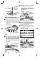
!
WARNING
To avoid possible fire or shock, make
sure that the wires are not pinched
between the light fitter assembly and the
light kit adapter plate. Pinched wires will
also cause the light fitter assembly to
mount crooked on the light kit adapter
plate.
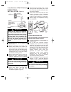
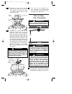
#10-32 x 5/16" PAN
HEAD BLADE SCREW
(3 per blade)
#10 FLAT BLADE
WASHER
(3 per blade)
FAN BLADE
BLADE
FLANGE
Figure 6
NOTE: Take care not to scratch fan
housing when installing blades.
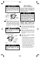
2. Position the bottom half of the
styrofoam packaging on the floor
(Figure 7). Turn the fan motor assembly
upside down onto the styrofoam in
preparation for mounting the fan blade
assemblies.
3. Carefully slide one blade assembly into
the motor housing assembly flange
slot. Attach the blade assembly using
two #10-32 x 5/16” oval head flange
screws (Figure 8). Make sure the
screws are securely tightened. Repeat
this procedure for the other four blade
assemblies.
Figure 7
FAN MOTOR ASSEMBLY
(Flange Slots Facing Up)
BOTTOM
HALF OF
STYROFOAM
Figure 8
88
BP7335 Palazzo 1/9/07 9:05 AM Page 8