


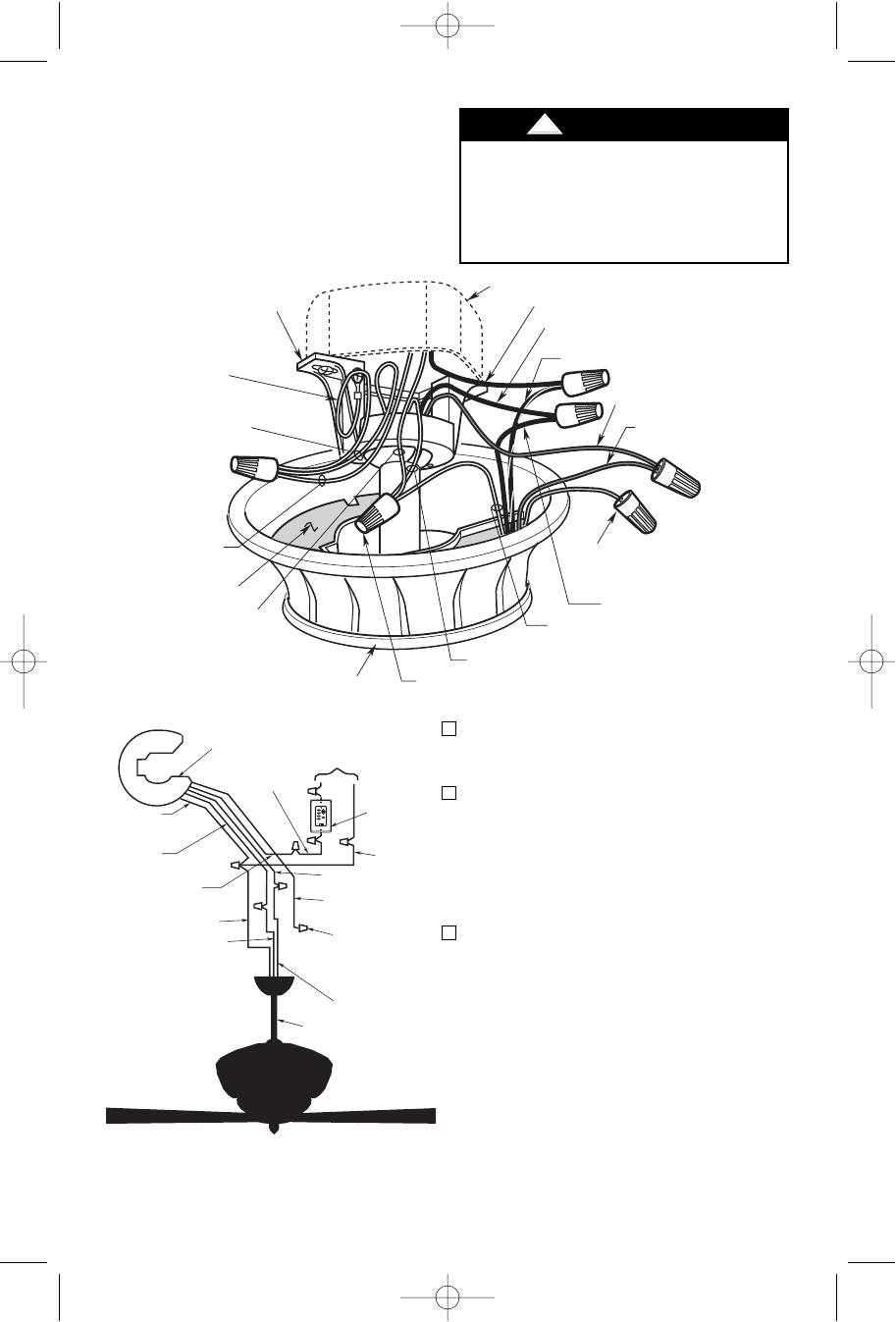
WHITE
SUPPLY
WIRE
BLACK FAN WIRE
SW105 RECEIVER
TO
110V
SUPPLY
SW113
FAN/LIGHT
WALL
CONTROL
CAP THE
YELLOW
RECEIVER WIRE
USING A WIRE
CONNECTOR
BLUE RECEIVER
WIRE
BLUE FAN WIRE
BLACK
SUPPLY
WIRE
WHITE
RECEIVER
WIRE
BLACK
RECEIVER WIRE
BLACK/WHITE
RECEIVER WIRE
YELLOW
RECEIVER WIRE
DOWNROD
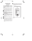
HI
MED
LOW
FAN OFF
ONOFF
REV
D/L
U/L
WHITE FAN WIRE
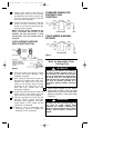
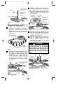
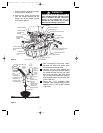
Figure 21
4. After connections have been made,
separate the white and green wires
from the black and blue wires.
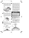
5. Carefully turn the wires upward and
insert them up through the open side of
the hanger bracket and into the outlet
box. Push the green and white wires
into one side of the outlet box; push the
black and blue wires into the other side
of the outlet box.
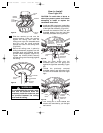
6. Screw two 1-1/4” threaded studs
(supplied in the loose parts bag) into the
tapped holes in the hanger bracket
(Figure 22).
12
OUTLET BOX
BLACK SUPPLY WIRE
BLACK/WHITE RECEIVER WIRE
BLACK FAN WIRE
BLUE FAN WIRE
BLUE RECEIVER
WIRE
CAP THE YELLOW RECEIVER WIRE
USING A WIRE CONNECTOR
CEILING COVER
WHITE RECEIVER WIRE
WHITE FAN WIRE
WIRE CONNECTOR
RECEIVER
WHITE SUPPLY
WIRE
SUPPLY GROUND
WIRE (GREEN OR
BARE)
HANGER BALL
GROUND WIRE
(GREEN)
HANGER BRACKET
GROUND WIRE
(GREEN)
HANGER BRACKET
BLACK RECEIVER WIRE
OPEN
PORTION OF
RECEIVER
HERE
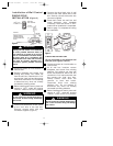
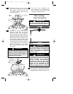
Figure 20
f. Cap the receiver yellow wire using a
wire connector (supplied).
g. Connect the green ground wires
from the hanger bracket and the
hanger ball to the supply ground
wire (bare or green).
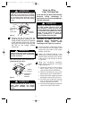
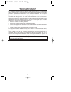
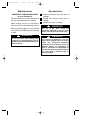
Check to see that all connections are
tight, including ground, and that no bare
wire is visible at the wire connectors,
except for the ground wire. Do not
operate fan until blades are in place.
Noise and fan damage could result.
!
WARNING
BP7335 Palazzo 1/9/07 9:05 AM Page 12