


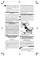
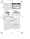
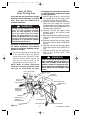
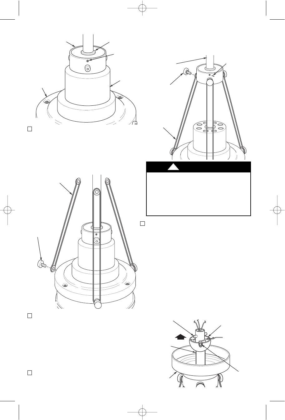
(Figure 11). Hold the rod support in
this position while tightening all six
decorative rod screws securely.
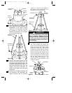
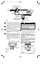
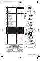
18. Place the ceiling cover over the down-
rod. Then reinstall the hanger ball
(Figure 12) on the downrod as follows.
Route the three 80” motor leads
through the hanger ball and slide the
hanger ball over the downrod. Position
the pin through the two holes in the
downrod and align the hanger ball so
the pin is captured in the groove in the
top of the hanger ball. Pull the hanger
ball up tight against the pin and
securely tighten the setscrew in the
hanger ball. A loose setscrew could
create fan wobble.
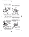
ROD SUPPORT
ASSEMBLY
MOTOR
HOUSING
GROMMET
(SCREWS
TOWARD
TOP)
COUPLING
COVER
Figure 9
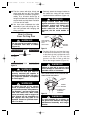
15. Using the decorative rod screws (sup-
plied), attach the three decorative rod
assemblies to the motor housing
(Figure 10). The decorative rods must
be oriented so that they lean in
towards the downrod. Do not tighten
the rod screws at this time.
16. Slide the rod support assembly up the
downrod until the threaded holes in the
rod support align with the holes in the
decorative rod assemblies (Figure 11).
Secure the decorative rods to the rod
support using three decorative rod
screws; do not tighten the rod screws
at this time.
17. Rotate the rod support assembly until
the decorative rod assemblies are
aligned vertically with the downrod
DECORATIVE ROD
ASSEMBLY
DECORATIVE
ROD SCREW
Figure 10
DOWNROD
CEILING
COVER
PIN
HANGERBALL
SETSCREW
Figure 12
8
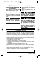
It is critical that the pin in the hanger
ball is properly installed and the
setscrew securely tightened. Failure
to verify that the pin and setscrew
are properly installed could result in
the fan falling.
!
WARNING
DECORATIVE
ROD
ASSEMBLY
DECORATIVE
ROD SCREW
DOWNROD
ROD
SUPPORT
ASSEMBLY
Figure 11
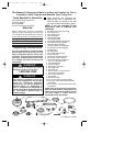
U.L. Model No.: CF200
BP7354 CF200 9/19/07 11:30 AM Page 8