


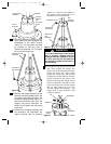
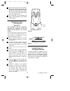
12. Tighten the setscrews (Figure 8)
securely while pulling up on the
downrod.
NOTE: The setscrews must be properly
installed as described above, or fan
wobble could result.
13. Make sure the grommet Is properly
installed in the coupling cover, then
slide the coupling cover over the
downrod until it rests on the motor
housing. (Figure 9).
NOTE: If you installed the 6” downrod,
the three decorative rod assemblies
and the rod support assembly will not
be installed. Disregard steps 14
through 17; proceed to step 18.
14. Make sure the grommets are properly
installed in the rod support assembly.
Then position the three screws in the
rod support toward the top, and slide
the rod support over the downrod
(Figure 9).
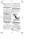
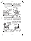
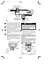
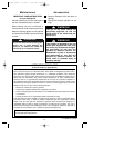
9. Carefully remove the fan assembly
from the lower foam pad. Turn the fan
assembly over and position it on the
lower foam pad with the fan blades
resting on the pad so that the top of
the motor faces up.
10. Remove the hanger ball by loosening
the setscrew in the hanger ball until
the ball falls freely down the downrod
(Figure 7). Remove th pin from the
downrod, then remove the hanger ball.
Retain the pin and hanger ball for rein-
stallation in step 18.
NOTE: If you have an eight-foot ceiling,
you will have to use the 6” downrod
(supplied) in order to maintain the nec-
essary blade-to-floor clearance of
seven feet.
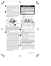
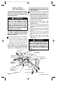
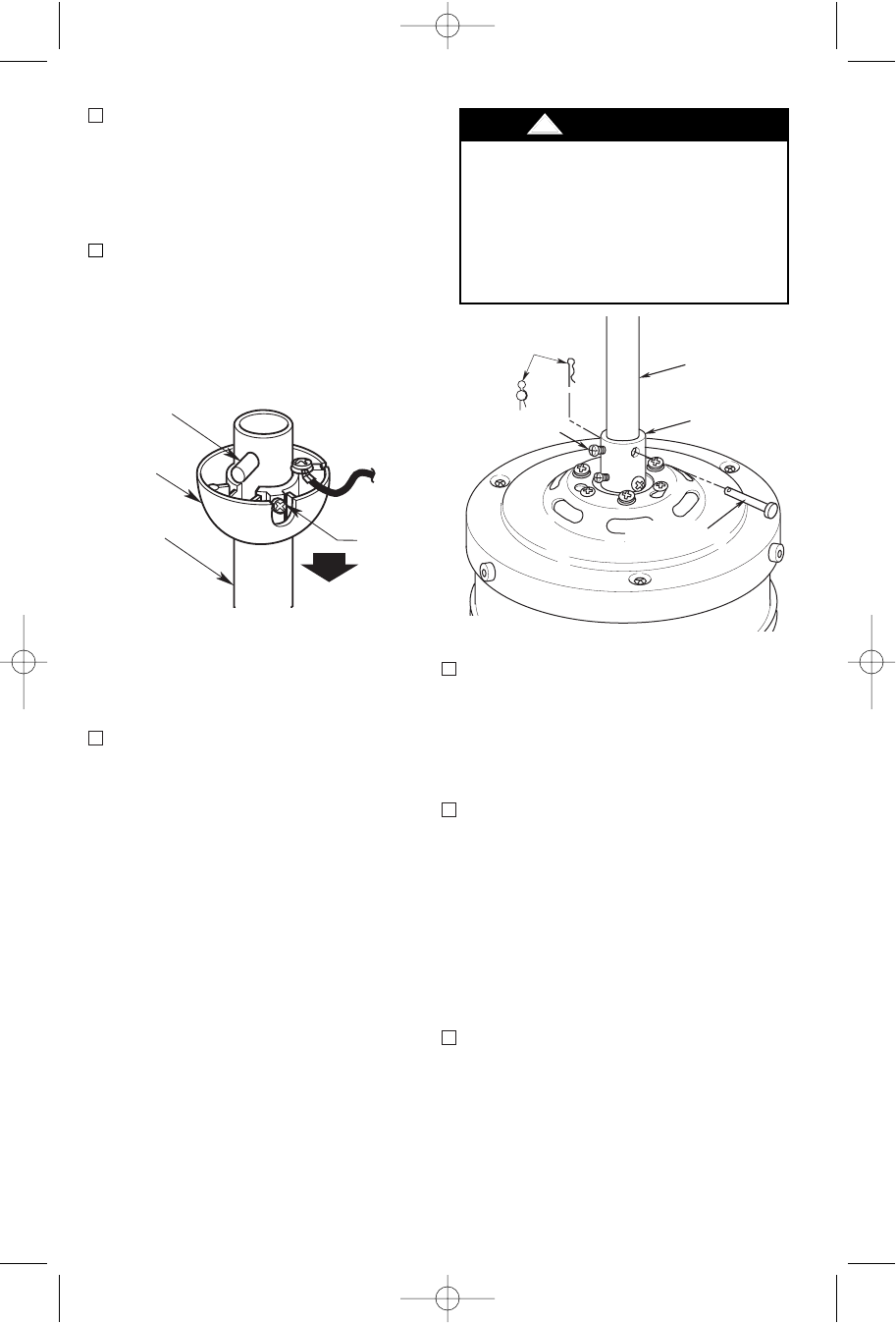
11. Unscrew the two upper setscrews
(Figure 8) until they clear the inside of
the motor coupling. Then separate,
untwist and unkink the three 80” motor
leads. Route the motor lead wires
through the downrod. Align the clevis
pin holes in the downrod with the holes
in the motor coupling. Install the clevis
pin and secure with the hairpin clip
(Figure 8). The clevis pin must go
through the holes in the motor cou-
pling and the holes in the downrod. Be
sure to push the straight leg of the
hairpin clip through the hole near the
end of the clevis pin until the curved
portion of the hairpin clip snaps around
the clevis pin. The hairpin clip must be
properly installed to prevent the clevis
pin from working loose. Pull up on the
downrod to make sure the clevis pin is
properly installed.
7
PIN
HANGER
BALL
SETSCREW
DOWNROD
Figure 7
DOWNROD
MOTOR
COUPLING
SETSCREW (2)
HAIRPIN
CLIP
CLEVIS PIN
It is critical that the clevis pin in the
motor coupling is properly installed
and the setscrews securely tight-
ened. Failure to verify that the pin
and setscrews are properly installed
(as shown in Figure 8) could result in
the fan falling.
!
WARNING
Figure 8
U.L. Model No.: CF200
BP7354 CF200 9/19/07 11:30 AM Page 7