


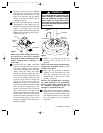
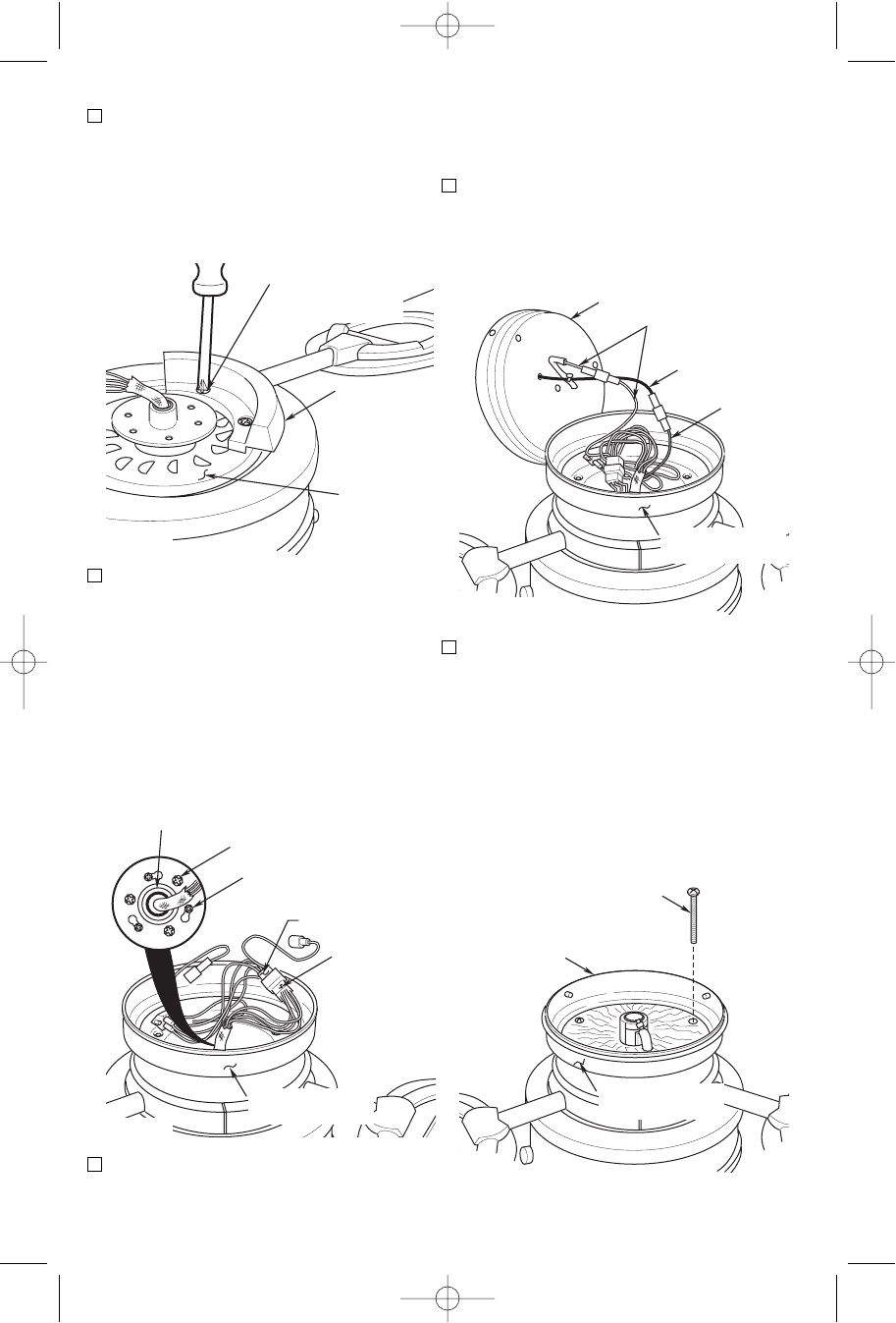
be mated correctly (color-to-color)
before they can be engaged. Make
sure the connectors close properly.
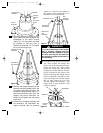
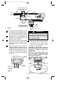
7. Connect the white wires from the light
fitter to the white wire in the switch
housing (Figure 5). Connect the black
wire from the light fitter to the blue wire
in the switch housing.
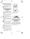
8. Position the light fitter into the switch
housing assembly (Figure 6) so that the
three mounting holes in the light fitter
align with the three threaded holes in
the switch housing. Install three 10-24 x
22mm pan head screws and tighten
securely.
CAUTION: Before installing and tight-
ening the screws, be sure there are no
wires pinched between the light fitter
and the switch housing.
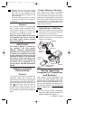
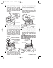
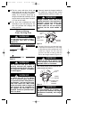
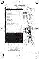
4. Position the blade flange on the motor
hub so that the screws in the blade
flange align with the two threaded
holes in the motor hub. Tighten the
two screws securely. Repeat this
procedure for the remaining two blade
assemblies.
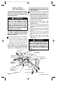
5. Insert the motor connector through the
center hole in the switch housing
assembly (Figure 4). Position the
switch housing so that the slotted holes
align with the smaller threaded holes in
the coupling. Then install three
8-32 x 12mm pan head screws with
lockwashers (supplied). Install three
1/4-20 x 11mm pan head screws with
lockwashers (supplied) in the larger
threaded holes. Tighten the screws.
6. Engage the connector of the switch
housing assembly with the motor con-
nector (Figure 4). The two connectors
are keyed and color-coded and must
BLADE
FLANGE
1/4-20 x 11mm PAN
HEAD SCREW WITH
LOCKWASHER (2)
MOTOR HUB
Figure 3
6
SWITCH HOUSING
ASSEMBLY
MOTOR
CONNECTOR
SWITCH HOUSING
CONNECTOR
COUPLING
1/4-20 x 11mm PAN HEAD
SCREW WITH LOCKWASHER
8-32 x 12mm PAN HEAD
SCREW WITH LOCKWASHER
LIGHT FITTER
SWITCH HOUSING
ASSEMBLY
WHITE WIRES
BLACK WIRE
BLUE
WIRE
LIGHT FITTER
10-24 x 22mm PAN
HEAD SCREW (3)
SWITCH HOUSING
ASSEMBLY
Figure 4
Figure 5
Figure 6
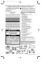
U.L. Model No.: CF200
BP7354 CF200 9/19/07 11:30 AM Page 6