


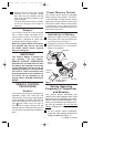
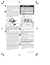
7. Screw the 75-watt (maximum) halogen
bulb (supplied) into the light fitter sock-
et (Figure 19). Do not touch the glass
bulb; use the porcelain base to screw in
the bulb, or wear soft gloves.
CAUTION: To avoid risks of burns or
other injury, assure power is off before
attempting to install or replace the
halogen bulb.
NOTICE: Do not touch halogen bulb
with bare hands. Fingerprints may
result in shorter bulb life. Remove
fingerprints with alcohol.
75-WATT
HALOGEN BULB
FLAT AREA
SOCKET
PIN
LIGHT
FITTER
LOWER
GLASS
Figure 19
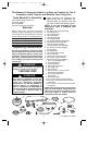
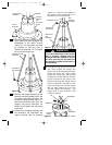
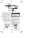
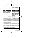
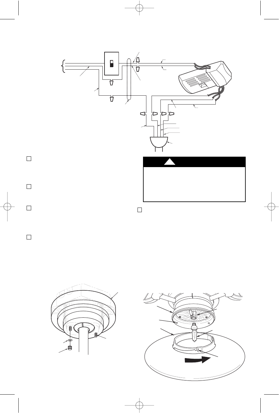
To avoid possible fire or shock, make
sure that the electrical wires are
completely inside the outlet box and
not pinched between the ceiling
cover and the ceiling.
!
WARNING
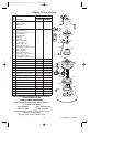
STANDARD ON-OFF WALL
SWITCH OR OPTIONAL SW101
WALL CONTROL
BLACK
BLACK
WHITE
RED
BLACK
WHITE
HANGER BALL
GREEN WIRE (GROUND)
FROM HANGER BALL AND
HANGER BRACKET
TWO-CONDUCTOR
CABLE (WITH
GROUND)
BLACK
(HOT)
WHITE
GROUND
TO
120-
VOLT
SUPPLY
WHITE
BLUE
WHITE
BLUE
Figure 17
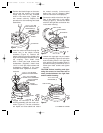
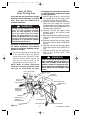
3. Push the wires and connectors up into
the outlet box while inserting the receiv-
er fully into the hanger bracket. Position
the antenna wire on top of the receiver.
4. Screw the two 1-1/4” threaded studs
(supplied) into the tapped holes in the
hanger bracket (Figure 16).
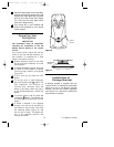
5. Lift the ceiling cover up to the threaded
studs and turn until the studs protrude
through the holes in the ceiling cover
(Figure 18).
6. Secure the ceiling cover in place by
sliding lockwashers (supplied) over the
threaded studs and installing the two
knurled knobs (supplied). (Figure 18).
Tighten the knurled knobs securely
until the ceiling cover fits snugly against
the ceiling.
THREADED
STUD (2)
CEILING
COVER
KNURLED
KNOB (2)
LOCKWASHER
(2)
Figure 18
U.L. Model No.: CF200
11
BP7354 CF200 9/19/07 11:30 AM Page 11