


3
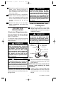
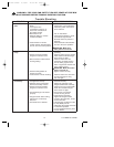
Tools Needed for Assembly
One Phillips head screwdriver
One wire stripper
One stepladder
Six wire connectors (supplied)
Materials
Wiring, outlet box and box connectors
must be of type required by the local code.
The minimum wire would be a 3-conductor
(2-wire with ground) of the following sizes:
Installed Wire Length Wire Size A.W.G.
Up to 50 ft. 14
50-100 ft. 12
This Manual Is Designed to Make it as Easy as Possible for You to
Assemble, Install, Operate and Maintain Your Ceiling Fan
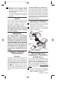
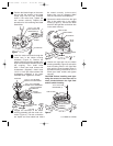
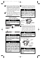
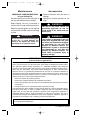
Unpacking Instructions
For your convenience, check-off boxes
are provided next to each step. As each
step is completed, place a check mark
in the box. This will insure that all steps
have been completed and will be help-
ful in finding your place should you be
interrupted.
Do not install or use fan if any part is
damaged or missing. Call Toll-Free:
1-800-654-3545
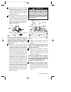
!
WARNING
This product is designed to use only
those parts supplied with this product
and/or any accessories designated
specifically for use with this product by
Emerson Electric Co. Substitution of
parts or accessories not designated for
use with this product by Emerson Electric
Co. could result in personal injury or
property damage.
!
WARNING
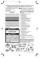
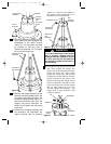
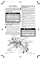
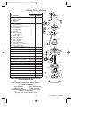
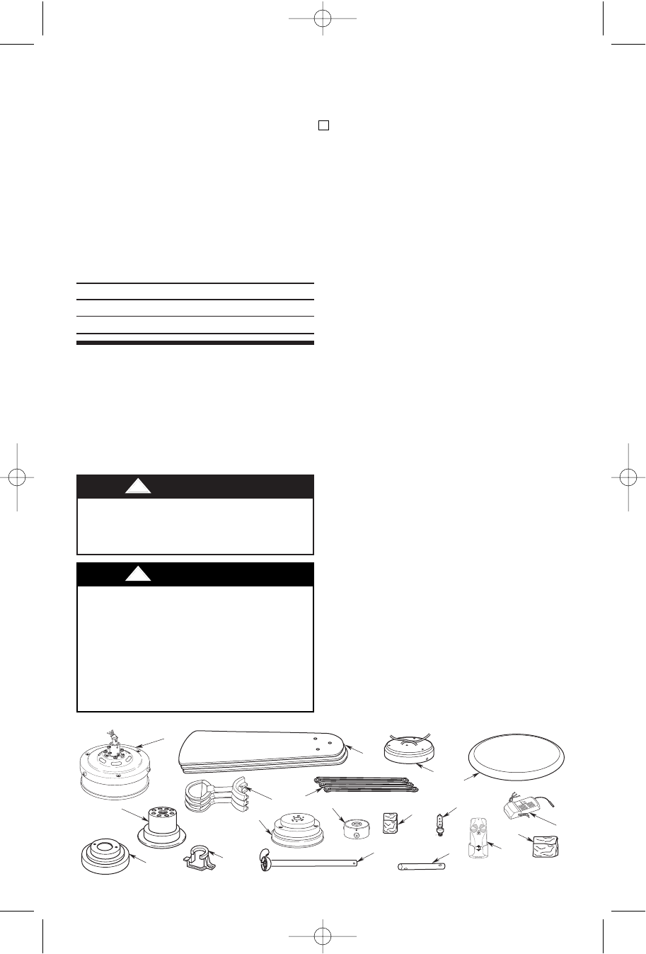
a. Fan motor and housing assembly
b. One ceiling cover
c. One coupling cover
d. Three fan blades
e. Three blade flanges
f. One hanger bracket
g. One hanger ball/downrod assembly
h. One switch housing assembly
i. One rod support assembly
j. Three decorative rod assemblies
k. Six decorative screws (bagged)
l. One light fitter
m. One lower glass
n. One 75-watt halogen bulb
o. One 6” downrod
p. One remote control transmitter
q. One remote control receiver
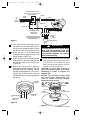
r. One loose parts bag, containing:
1. Two 1-1/4” threaded studs
2. Two knurled knobs
3. Two lockwashers
4. Seven wire connectors
5. One hairpin clip
6. One clevis pin
7. Seven 1/4-20 x 11mm pan head
screws with lockwashers
8. Ten 10-24 x 9mm truss
head screws
9. Ten fiber washers
10.Four 10-24 x 22mm pan head screws
11. Four 8-32 x 12mm pan head screws with
lockwashers
12.Four 1/4-20 x 11mm pan head screws with
lockwashers
NOTE: Place the parts from the loose parts
bags in a small container to keep them from
being lost. If any parts are missing, contact
your local retailer or catalog outlet for
replacement before proceeding.
D
J
B
HI OFF
LOWMED
I
C
L
O
G
H
M
Q
R
A
E
N
F
P
K
1. Open styrofoam unit containing fan.
Remove top half of styrofoam unit.
Remove parts and check to see that
you have received the following parts:
NOTE: If you are uncertain of part
description, refer to exploded view
illustration.
U.L. Model No.: CF200
BP7354 CF200 9/19/07 11:30 AM Page 3