


Preset Memory Feature
Your remote control receiver is equipped
with a preset memory feature. The receiv-
er will remember the light intensity and fan
speed when the light and fan are turned off
from the wall switch. When the wall switch
is turned back on, the lights and fan will
resume operation as they were prior to the
switch being turned off.
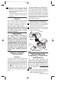
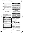
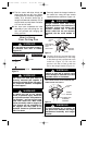
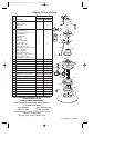
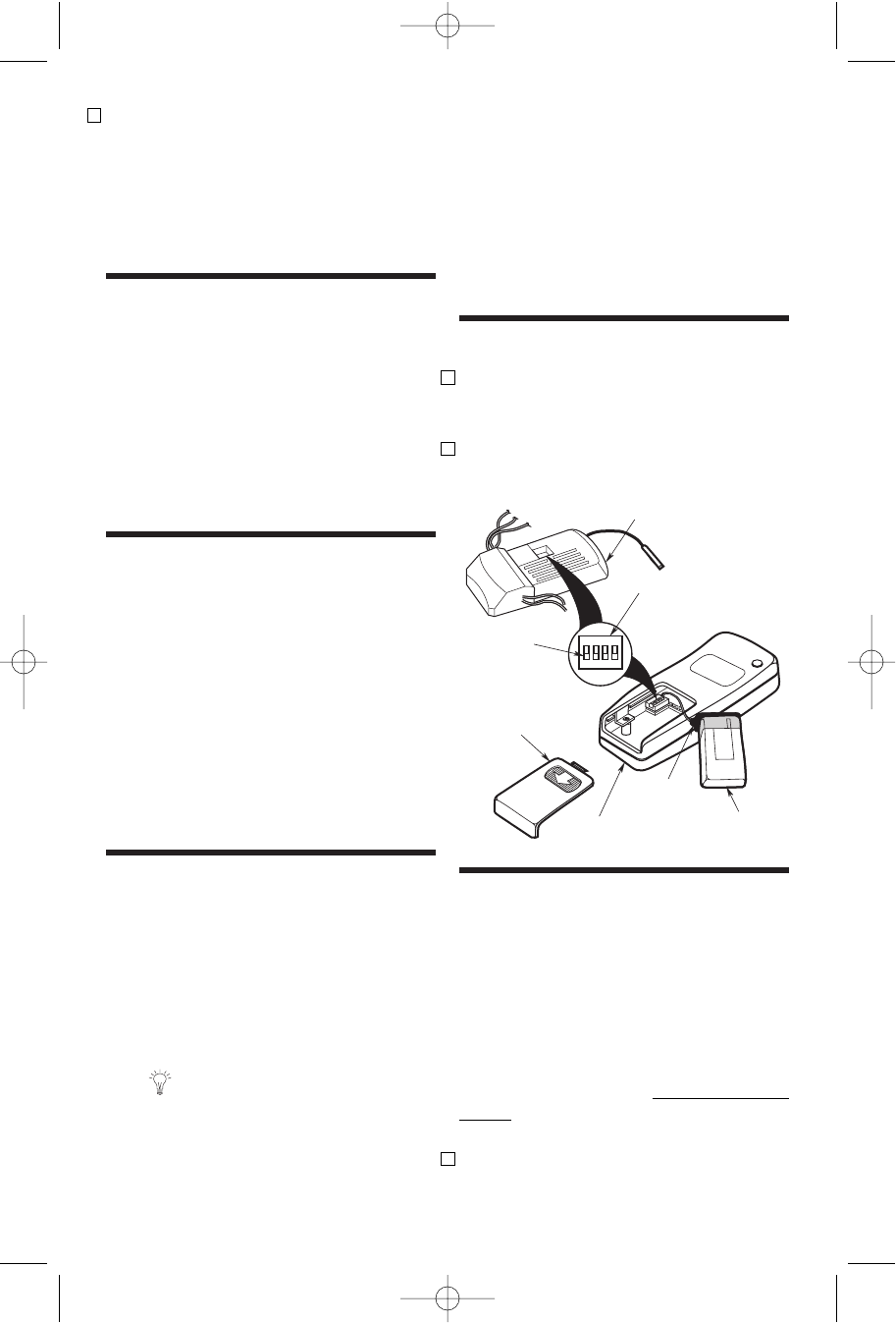
Installation of Battery
1. Remove the battery cover by pressing
firmly below the arrow and sliding the
cover off the control (Figure 1).
2. Engage the connector in the transmitter
with the terminals of a 9-volt alkaline
battery (not supplied).
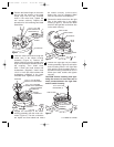
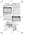
2. Remove the fan motor and housing
assembly from the protective plastic
bag. Place the fan assembly into the
lower foam pad with the bottom of the
motor facing up.
The lower foam pad serves as a holder
for the fan during the first stages of
assembly.
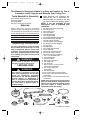
General
Your Emerson ceiling fan comes equipped
with a remote control transmitter and a
remote control receiver. This remote con-
trol systems is designed to control your
ceiling fan speed and light intensity.
NOTE: An optional SW101 Wall Control
(not supplied) may also be used with
the remote control receiver supplied
with your ceiling fan.
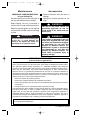
IMPORTANT
This Owner’s Manual is divided into
two sections. The first section,
REMOTE CONTROL PROCEDURES,
describes how to install the 9-volt alka-
line battery (not supplied) in the remote
control transmitter, and how to set the
operating frequency of the transmitter
and receiver. These instructions must
be performed prior to the installation of
the ceiling fan as described in the
second section, CEILING FAN PROCE-
DURES.
REMOTE CONTROL
PROCEDURES
General
The remote control system is designed to
separately control your ceiling fan and
light intensity. There are four push buttons
on the transmitter (HI, MED, LOW, OFF) to
set the fan speed and turn the fan off. The
light push button turns the light on
and controls the light intensity. The red
indicator light will illuminate while any but-
ton is pressed, indicating that the battery is
good.
4
BATTERY
COVER
BATTERY
B
a
t
t
e
r
y
BATTERY
CONNECTOR
REMOTE CONTROL
TRANSMITTER
SWITCH
LEVERS
CODE
SWITCH
1 2 3 4
ON
RECEIVER
Setting Operating
Frequency of Transmitter
and Receiver
Your remote control transmitter and
receiver have code switches which must
be set on one of 16 possible code combi-
nations. The four levers (numbered 1, 2, 3,
and 4) on the switches are factory-set in
the ON (up) position. Do not use this
setting. Change the switch settings as
follows:
1. On the remote control transmitter,
locate the code switch just above the
battery compartment (Figure 1).
Figure 1
U.L. Model No.: CF200
BP7354 CF200 9/19/07 11:30 AM Page 4