


8
HM1 W RHRC G Y HM2 6
W
RH
1
2
3
HM1 HM2
6
Y
G
W
RC RH
E
H
J
I
M
K
L
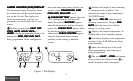
WIRING DIAWIRING DIA
WIRING DIAWIRING DIA
WIRING DIA
GRAMSGRAMS
GRAMSGRAMS
GRAMS
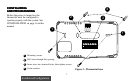
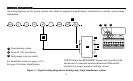
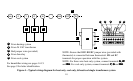
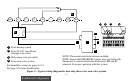
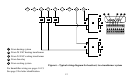
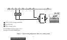
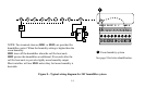
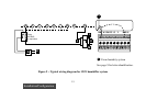
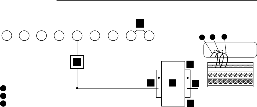
All wiring diagrams are for typical systems only. Refer to equipment manufacturers' instructions for specific system wiring
information.
NOTE: Ensure that RED RH/RC jumper wire (provided with
thermostat) is connected between thermostat's RH and RC
terminals for proper operation with this system.
1
From heating system
2
From 24 VAC transformer
3
Red jumper wire (provided)
For humidifier wiring see pages 14-15.
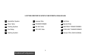
See page 9 for letter identification.
Figure 3 – Typical wiring diagram for heating only, single transformer system